It’s pretty clear there’s a problem with auto-leveling. There are people here and in the FB group constantly talking about ruined and gouged build plates.
I’m awaiting my 350 - but now anxiously as well as eagerly, since I’m not sure it’s going to ruin the build plate on my first print.
I’ve seen the SM team engaged on these forums, and they seem to be trying to fix it, which is great.
Has there been an official announcement from SM on the problem? I feel like we need an update, specifically with:
What is the root cause? Have they found out why so many users have the same problem?
What is the fix? (The real, permanent fix, not workarounds)
Will they replace the beds for people affected who had their plate ruined?
Will the fix be applied to new machines leaving the factory, or will we have to do some sort of update when we receive it? (I probably won’t see mine until May. )
Have they officially posted an answer to any of these?
waiting to hear as well seem as though they should warranty the ones that have issues!!! Anyone form snapmaker care to chime in any time would be great!!!
My build plate got damaged after some 15 prints without issues. The snapmaker support asked me to send the log files, but as I recalibrated the printer immediatly after the problem occured, there is no usable trace in the logs
It seems that Snapmaker did not find the cause of the problem yet …
Hi all, sorry for the inconvenience. We have analyzed many cases about the printing module gouging issue, and we have reproduced it sometimes. There many causes like the position of proximity sensor, thickness of print sheet or the firmware. Here we offer a guide for the users to adjust the height difference between the nozzle and the proximity sensor.
First, you can update the software and the firmware via the following links:
Please do as follows to adjust the proximity sensor(for A150 as well):
It seems that you need to adjust the proximity sensor and check the platform.
Normally, when the nozzle is close to the surface of the printing, there will be a red dot in the nozzle.
Please do a calibration process, and record the process to check if the proximity sensor works during the process.
1, Please check if you have assembled the platform in right method. Here is an image for you to refer to.
2, Please adjust the height difference to about 1 mm and then tighten the screws of the probe sensor. Connect the machine with the PC via the provided USB cable in the same time.
2.1, As for the 1 mm height difference, you can use a piece of credit card as the standard.
2. 2, Power off the machine and assemble the module in place as shown in the following picture. Loosen the screws of the probe sensor and put a credit card below it. Adjust the height difference and make sure the values of it is about 1 mm, and then tighten the screw.
3, Please be noted that you need to record all the information of the software from the booting to the end of calibration process, which is greatly helpful for us to troubleshoot this issue
4, Open the software Snapmaker Luban and enter the command “M502“ → “M500“ → “G28“ in order and operate each of them. Change the value of time-out to 15s or 30s so that we can record the settings.
5, Do the calibrations process by using the touchscreen.
6, Please do not cut off the connection between the machine and the PC during the calibration process.
Edwin
Thank you for this post. I used this process to solve my calibration issues. Can I suggest the following edit on your post;
Step 2 describes how to change the proximity sensor. Before step 3, add a step (maybe 2.3) to advise the user to put the module back into the normal mounting position (before calibrating).
Regards
Waldo
Dear Edwin,
Not everyone is an expert.
It would help if your instructions were more clear. PLEASE think in terms of a newbee not a techie!
For instance, you are saying “Power off the machine and assemble the module in place as shown in the following picture.” Since the machine is powered off, do you mean we should MANUALLY push the module down and to the centre as in your photo? Please clarify.
Your photo shows a different module than the one I have on my Snapmaker A350! I have only got 2 screws on the side of my module (A350). Are they both for the sensor?
I saw the video in project update #17 but it did not help. if anything it is ever more confusing. So we are supposed to have a 0.05 mm clearance between nozzle and bed and 0.2 mm between sensor and bed, so how do you do this using the credit card exactly? How thick is a credit card? How do you know the nozzle is 0.05 mm above the bed before you start to play with the sensor height if the machine is off? And even if it is on, since the sensor is not yet set it cannot help you get to that point. Do we need a feeler gauge for this? Is there one in the kit provided? Is the white card that was in the kit 0.05 mm? I am totally confused here.
It is really frustrating and confusing when you give insufficient background detail, as we then risk damaging our machines. I wish you could explain the process in a simpler way. One step at a time in baby steps even, without assuming anything.
Some general history here: Basically the sensor was too high above the nozzle. These are steps to bring the sensor lower to the nozzle. It doesn’t need to be exact, just “about 1 mm”
It’s really important to update the firmware and also Luban - ESPECIALLY the firmware, before you do this.
I will try and help clarify this for you, so you get a fast response and can keep rolling, since it seems you are working on it today, which is awesome. There is some lag time between the states and China.
Yes. once the machine is powered off the stepper motors are no longer actve and you can manually move the X-axis(horizontal) up and down. Just like during original assembly, use both hands, one at each of the vertical bars.don’t go xrazy with force! you don’t need too much to move them. Also, good idea to move the bed so the nozzle is in the center at this point as well. Same way, manually. If you are not confortable doing it manually, you can use the Luban software with e comuter hooked up on the USB to get it close.
The picture is from the back side of the module. I hope this clears up your confusion with the image, otherwise you really do have a different module somehow!
NOTE HERE: There should be a step between the 2 and 3 steps. Once you have completed all of step 2, you should reassembe the module back to the original position before continuing to step 3. I would recommend moving the x-axis to maximum height at this point.
This is very good feedback for the snapmaker team, but I will elaborate. The white calibration card is for 3d printing. It is .1mm thick, but you don’t need it for this. You could put it there if you wanted to, but it’s not necessary. What IS necessary - you want the nozzle down on the very center of the bed. Just touching. Make sure it’s not digging in. Now, you put the credit card under the sensor area. The picture is taken from the back of the machine.
Thank you so much ! Now I am starting to see the light.
So…
I need to remove the module and reattach it as shown so that i can access the screws.
I can move the module down until the nozzle just touches the bed
I then adjust the sensor using the credit card
Brilliant and very clear!
I have not done this yet, because what I did today as part of the investigation was to:
Re-installed firmware 1.8 on the machine and 3.5 on Luban
Ran an auto calibration using 5 x 5
Tried to print a calibration STL (attached)
The nozzle extruded material about a full centimetre above the bed. I stopped it.
i ran a full manual calibration of all 25 points and printed the STL again
This time the STL printed but not all were good quality. I took various photos.
Unfortunately I am unable to interpret the meaning of the artifacts but I can submit these if necessary. Would “support” or someone here be able to guide me on this please?
Now that i know how to adjust the sensor, i will do that and run the auto calibration again and then rerun the test calibration print.
However I have some doubts because a 5 x 5 is not as accurate as a 7 x 7 or 8 x 8 and some of the artifacts were towards the extreme edges.
I saw some expert users who used this grid and sent G code to set the Z for particular points to fix issues. Can we maybe have some kind of tutorial showing (a) what a “bad” first layer looks like and what it “should” look like and how we can get there by tweaking G code directly and passing on the coordinates and desired Z?
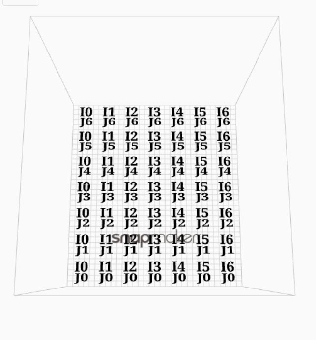
Here is the calibration grid I used. Maybe we can use this for all users as a central reference point and show people how to fine tune accordingly?
I appreciate your support Edwin. Just keep in mind a lot of us are beginners… but now NilartPax has explained it well so I can follow what I need to do. Please do read my reply though as even if I do get it to print on the bed, this does not mean it will be a good first layer and that is what I need to achieve. I have seen other printers (cheap ones) where you don’t even see the layer lines, or at least hardly… that’s where I want to get to. I think the 5 x 5 may not be enough for this. is it possible to take it further say to a 7 x 7 or even 8 x 8 calibration matrix? Thanks.
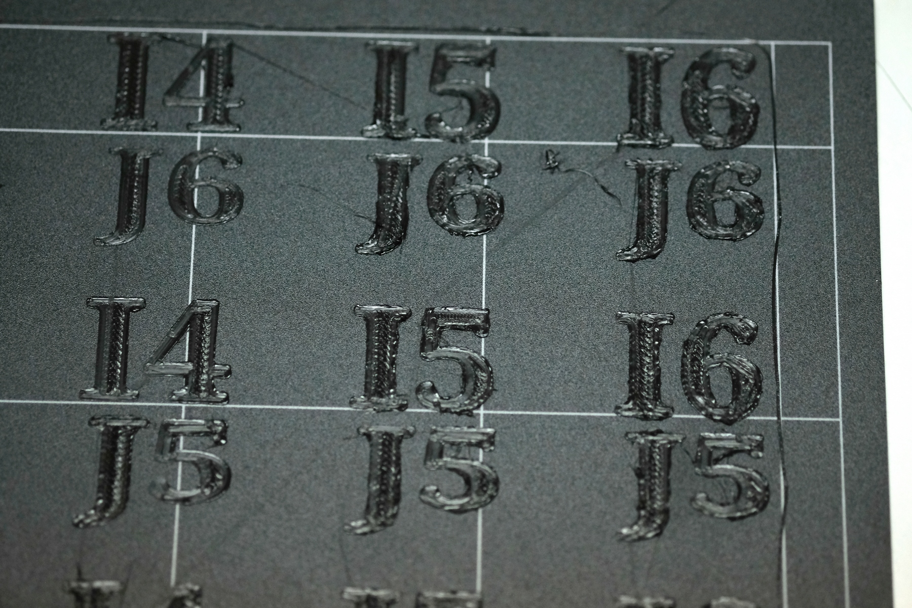
Here is an example of what I mean. This was before I did the sensor adjustment and recalibration. is it supposed to be like this ? I marked various points with a red arrow to show where I am not sure about the output… In some cases it is as if the nozzle has ploughed through the numeral, I did see the filament go backwards through the nozzle so I suppose Z retraction is happening… In some cases there is clearly too much material - maybe I should have reduced nozzle flow to 90% or even less? Still, I suppose I should really fix the sensor position and do this again before touching anything else. Thanks.
Hello everyone, I assemble my printer I check all cables it’s in good position. First time when I turn it on 3D printer module go down till make a damage on my heating bed, ant that happen from first step on guide when it’s automaticty start doing auto calibration. Later O try to take out that heated bed, for check how much he’s gonna go down so he’s go full down. Maybe somebody know how I can fix that. I think to put laser module and the start printer cause on laser are camera so I think when he see where is his minimum point, maybe it’s calibrate properly and then I can install newest software update. Thanks for answer and have good weekend
I think I may have found another potential reason that for 3D print bed gouging:
There are two types of M4 x 10 screws - Socket Head and Flat Head. The print on the bag is quite small, and that’s the only indication that you have one bag vs. the other.
If you use up the Flat Head screws in assembling the machine, and instead use Socket Head screws to attach the heated bed to the platform, you’ll have an uneven surface.
I found the text EXTREMELY small and non-obvious, and in fact put my heated bed on with 20 socket head screws - when it requires 22. I looked in the toolkit and found the other bag of M4 x 10s, and happily installed the last screws.
I noticed that most of my screws were not counter-sunk - they were poking up above the surface of the heated bed. But then I noticed that two of them WERE counter-sunk, leaving a nice, flat surface for the magnetic print bed.
That’s when I realized - I had used 20 socket head screws, and then grabbed the last two from the Flat Head bag.
Snapmaker - you REALLY need to make it much more obvious that there are two kinds of M4 x 10 screws. It’s CRITICAL to use the Flat Heads on your heated bed, or you’ll have hills in the print surface.
I wonder if some of the people having gouging issues only intermittently are putting the bed on and taking it off, and sometimes accidentally using socket heads, and sometimes correctly using flat heads.
EDIT: I know this is my fault since I missed it in the manual, since a bunch of people on the FB forum were…er…kind enough to point that out. I’m just trying to point it out to others, that’s another detail you can miss.
I started my first print after following the instructions for bed leveling (which is one of the main reasons I picked up the Snapmaker. automatice bed leveling), then started my print.
It looked like the first layer was doing a nice VERY flat 1sy layer so I let it run. However, that very flat first layer was actually the print head starting to gouge the black print bed. I partially attribute this to the sample PLA sent being black. If it was white or some other contrasting color I would have known right away that something was wrong because I wouldn’t see any white filament. I finally caught it when I went to check on it and saw what was going on and stopped it. I was printing some face mask clips for my wife and most of them (3 out of 4) left a light gouge of a few layers but no filament. It almost looks like burn-in that you would get form leaving a phone screen on too long, but it’s defiantly cut into the bed.
One clip that was printing on the front left looks like it dug in AND also left a few layers of black filament. It’s dug in pretty well so I doubt I’d get it all out.
Before coming here I flipped the bed and put some parchment paper under it in case the bed heating up started to melt any of the filament and recalibrated. This time I fudged the instructions a bit and instead of stopping when the calibration slip starts to fold up, I raised it by .05mm (or whatever the lowest is) and then tried pulling the slip all the way out and pushing back in. If I couldn’t push it in from the outside, I raised it again and then saved the config.
I then started a new print and so far it is working better (I won’t really know until it’s done.
Yeah, bummer. This seems to be the #1 complaint with people - bed gouging.
Unfortunately, there are a number of root causes, and their documentation is not quite up to snuff.
Sounds like you sorted it out - good on you.
I don’t mean to downplay the disappointment, but I wouldn’t worry about a gouge that was the depth of one layer - you can put blue painters tape over it to give a smooth surface again, and hopefully it should be good. You can also flip the print surface over and use the other side.
I’ve done 3D printing for a couple of years, and unfortunately, gouged print beds are super common, in my experience.
My advice: whenever you’re starting a new leveling process, or a new print, stand there with your hand on the power button until you’re sure you’re in the clear. The safest bet is first layer is fully laid down, but that could take 10-15 minutes to an hour for a big print. Still - I would not leave the printer unattended until at least the second layer.
 )
)


