Keywords:U1 How to adjust the pick & park coordinates
Or you can follow these more detailed pick-and-place coordinate steps to adjust your Toolhead
(PS: based on user feedback, the software team plans to release a new on-screen toolhead-coordinate-calibration feature next week).
-
Ensure all toolheads are returned to the rack and the red marks on each toolhead latch are no longer visible; if you cannot park a toolhead via the screen, follow the manual toolhead-parking guide.
-
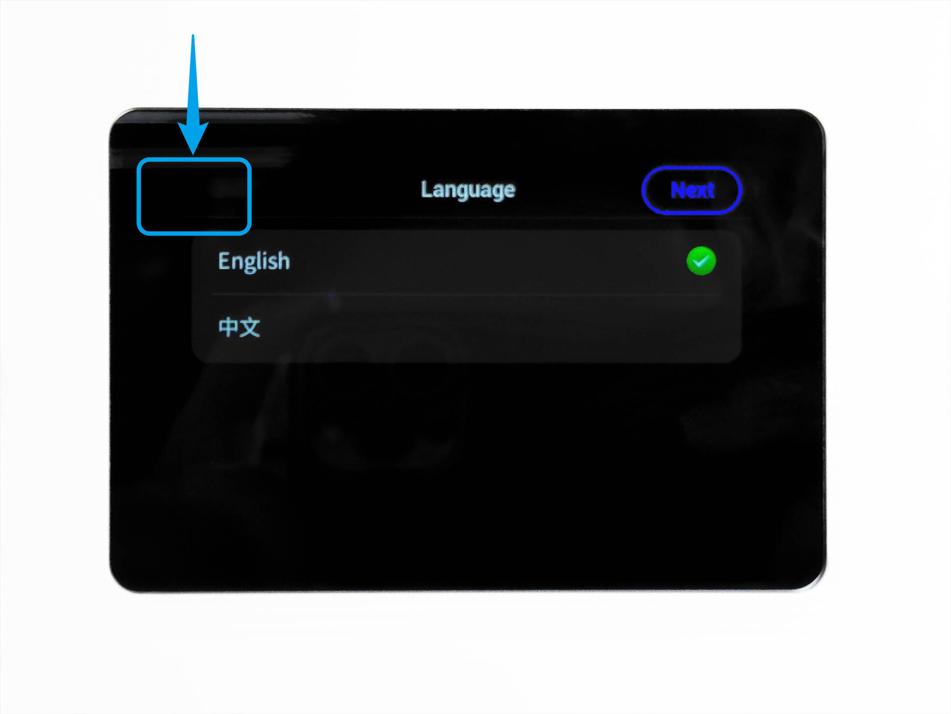
If you encounter an initialization error during the pick-and-place coordinate calibration, long-press the blank area in the upper-left corner of the screen to skip it and go directly to the home page.
-
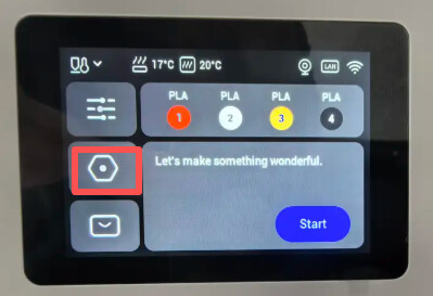
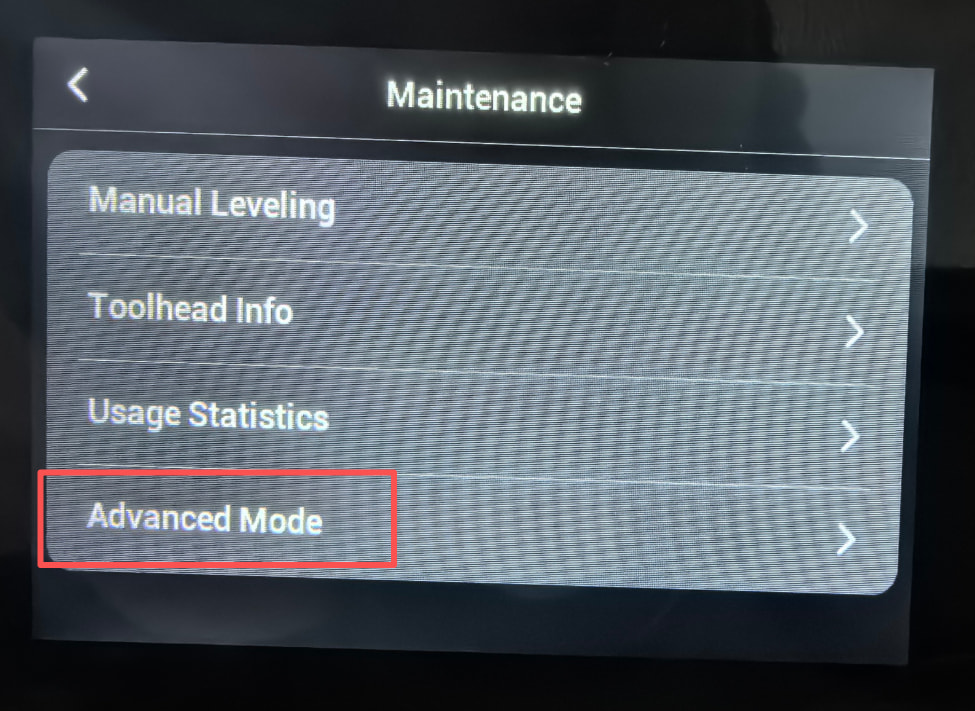
In Settings → Maintenance, enable Advanced Mode.
-
Prepare a computer/tablet/phone and connect it to the same Wi-Fi as the U1 (same local network).
-
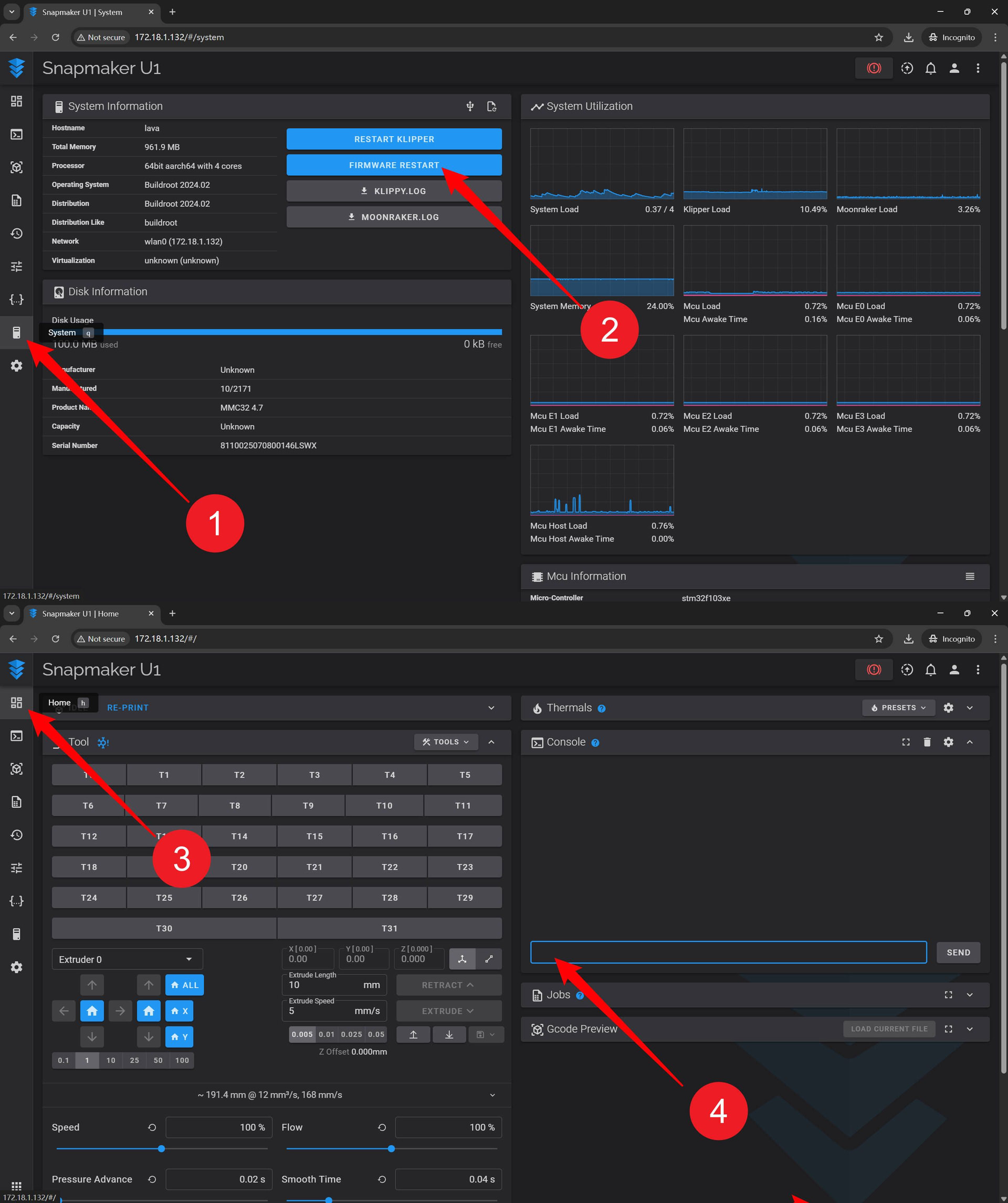
Open the browser, enter the IP address of U1 as shown in the image (you can check it in Settings → Wi-Fi), and go to the Fluidd interface.
——————————————————————————————
Necessary notes.
-
Pick/place-head coordinates refer to the (X,Y) position the toolhead changer travels to when performing pick/place operations; the actual coordinate system is shown in the illustration.
-
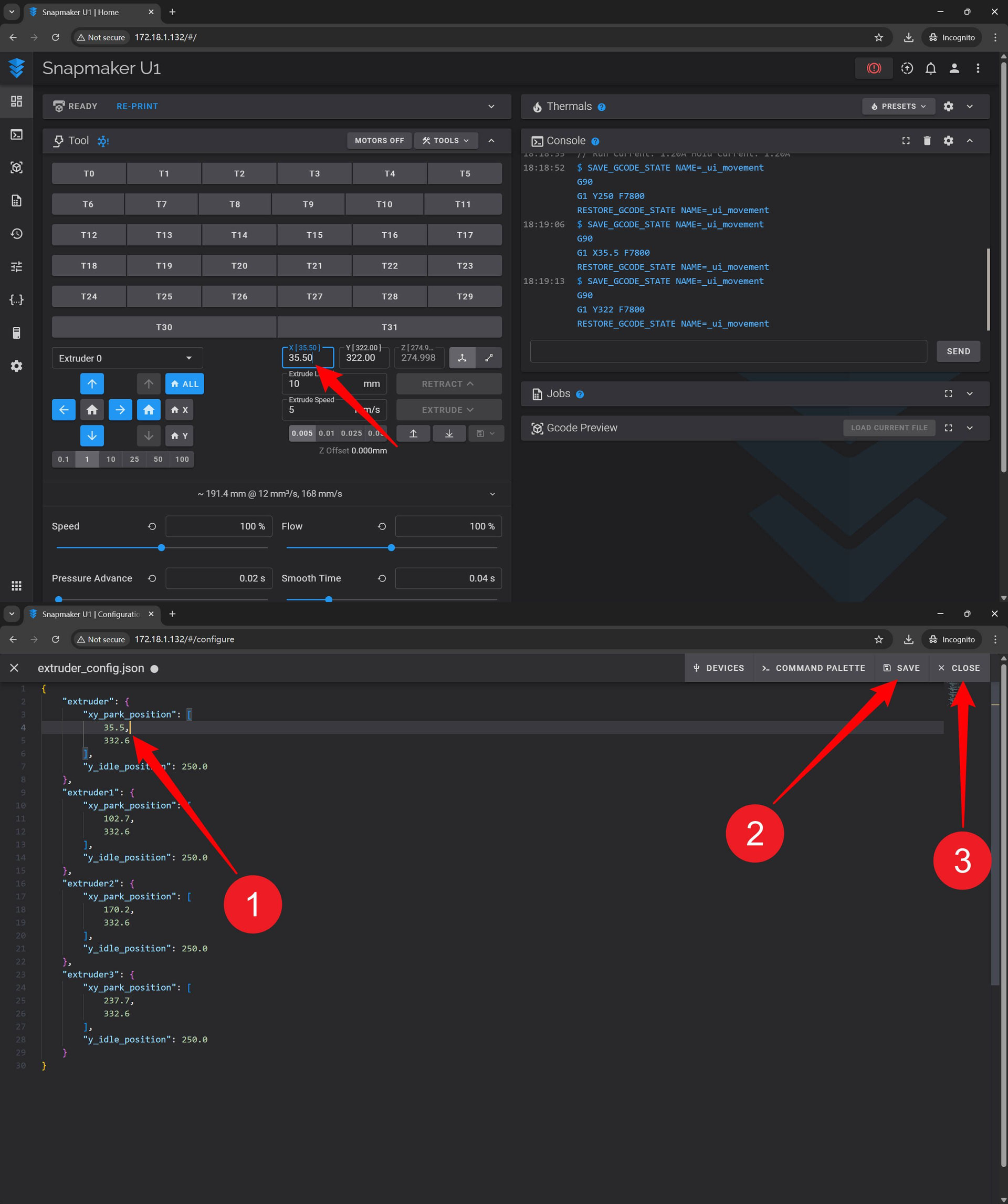
Click in order: Configuration → persistent folder → extruder_config.json → Edit to view the current pick-and-place coordinates for all four toolheads. (It’s recommended to take a photo of the IP for backup.)
-
When pick-and-place fails, if there’s no hardware issue, it’s usually the X value in the (X, Y) coordinates that’s problematic.
Replace the four pick-and-place coordinates here with:
(X0,Y0) (X1,Y1) (X2,Y2) (X3,Y3)
We can adjust the target values of the toolhead pick-and-place coordinates based on the actual tested coordinates:
4. For example, to calibrate the pick-and-place coordinates of Toolhead 0 (X0, Y0):
Enter the safe coordinate values for X0/Y0 in the input box: (X0, 300), which is (34.4, 300). Press Enter to move the toolhead changer to the default safe position for the corresponding toolhead.
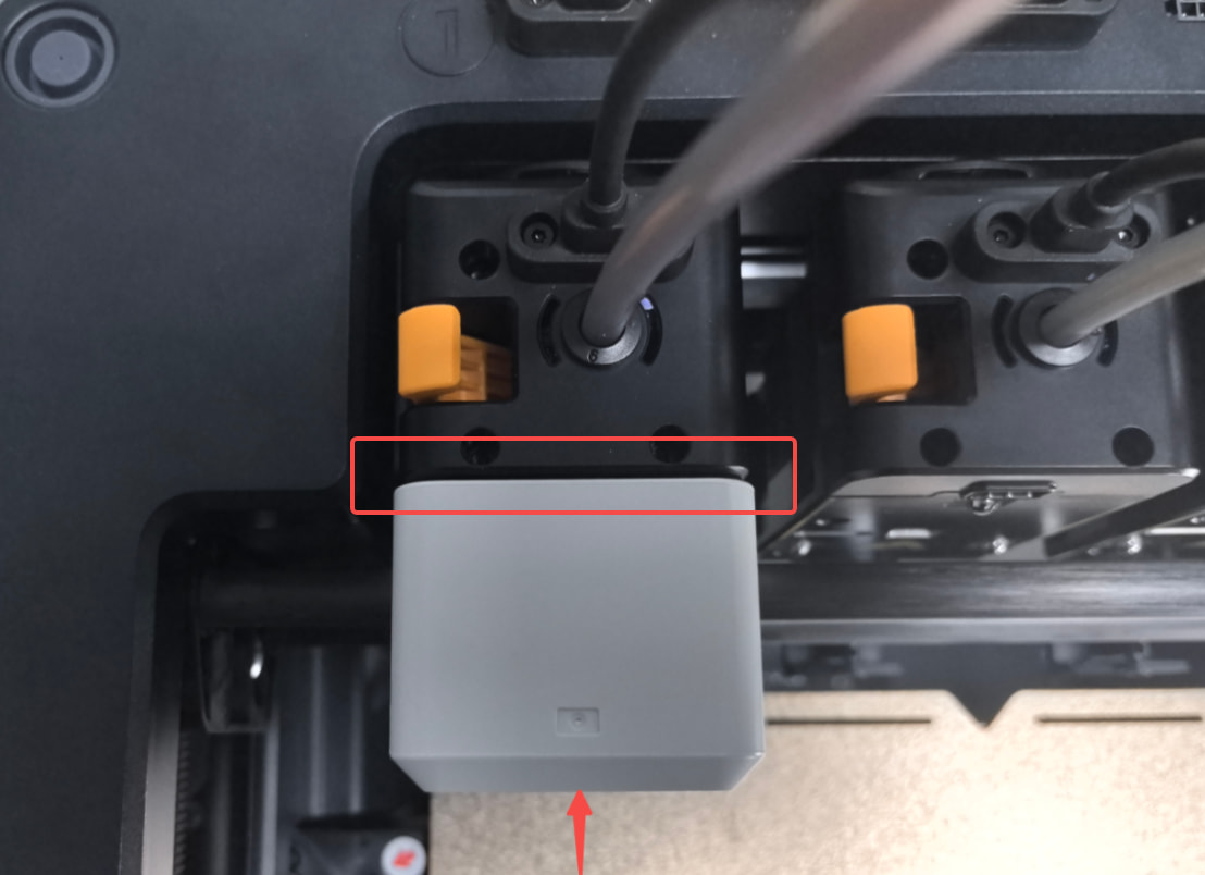
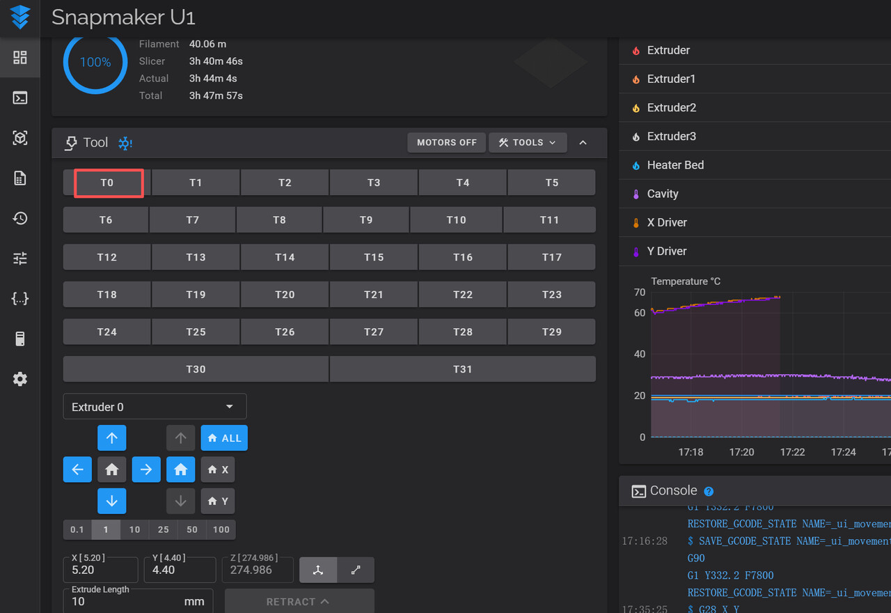
5. Continue using the browser to observe and move, controlling the positioning pin of the toolhead changer to better insert into the toolhead hole (as shown below). At this point, it indicates that the X coordinate is correct.
6. Keep controlling the toolhead changer and move the Y-axis toward the toolhead; stop when it reaches the position circled in red in the image and sits flush. Read the X0, Y0 coordinates at this moment and update them in the Tool0 field.
Generally speaking, any coordinate shift will be within 1 mm.
7.On the System page, click FIRMWARE RESTART. After the firmware restarts, go back to the Home page and send the pick/park command in the Console to verify if the updated coordinates work.
8. Verification: Return XY to zero in the browser, then cycle through T0–T3 and confirm the toolhead you just calibrated can pick and place normally.