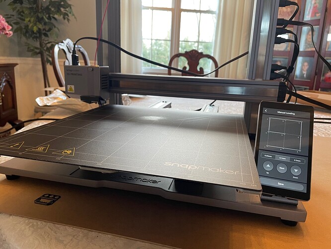
When I run the calibration procedure on my new A350 all of the test points are offset to the left and forward of the center position on the printed grid by about 15-20 mm. When I ran a couple of test prints they were similarly not centered on the bed. I’m pretty sure my bed is assembled according to the directions; it’s centered between the vertical linear tracks at least.
I looked in the settings for a manual adjustment for centering the head but didn’t see any. Is there a way to manually set the center point? When I get around to trying the laser or router I don’t want to be guessing where to place the center of the material.
Bump. I just received my A350 and I have the same issue. The bed cant level because the nozzle is off the bed on the left side.
The sensor is to the right of the nozzle. Is the sensor off the bed or just the nozzle?
-S
I went to take a picture of it this morning, and it kept the nozzle on the bed all the sudden, but was still very off-center. I will try and get it to print and report back.
I am having this issue as well - bump
Share photos and settings and/or screen captures or we can’t help you.
-S
I just received my A350 yesterday, and have the same issue.
The calibration (auto or manual) is consistenly off to the left, and the z-axis adjustment at the end does not occur at the ‘center’.
I see no way to adjust this.
The nozzle itself is not the point that is measuring, the sensor is off to the size, so this is why.
Auto calibration was not working, so I am trying manual calibration.
How do you perform the paper height test when the nozzle is not even close to the build platform?
In the photos, you will see the ‘manual calibration’ touch screen, and the position of the nozzle when attempting to measure the first point.
Look at your last photo, and mount your Y modules correct it seems not beeing so.
Check over the hole build!
Agreed, your linear modules are not mounted to the base correctly, they are supposed to fit in that rectangular groove
Snapmaker 2.0 bed levelling issue - Snapmaker 2.0 - Snapmaker: where creation happens
You guys are like hawks!
That was it. Thank you so much!
No problem everytime again.
I effed that up on the initial setup as well. The manual shows an on-end view where the linear modules are clearly in, or not in, the groove. But in practice, the grooves are not visible on-end, which makes it seem like all is okay, as the linear modules aren’t noticeably canted or anything. My own mistake was overshooting a groove in the Y direction.
thats ok alot of poeple do it, the book isnt very great about it thats printed, so they changed the digital publication of it
I made the same mistake when I started to put it together… the pictures in the setup guide had me thinking the rails hang off the back! Luckily I fixed it after I turned the page to the next step.
You guys are the best!
I can’t believe you got that from a close look at the photo.
I thought I had been so careful with the build, too. The most frustrating part was that it did work, and I got some decent looking parts, but the slight angle of the y-axis made calibration difficult and 1st layer adherence trickier than it had to be.
Anyway, I’m just glad it’s working well now!
The first thing that we ask is can we see pictures of assembly, because it happens so much - because the book is poorly illustrated hehe
I am also having the issue of centering the work on the platform. This one did not clear the handle of the mug and messed up bad shifting the magnetic platform.
Do you have the correct model of SM selected in Luban?
-S


