I agree with @sdj544 if it seems to do fine across all of them, continue going faster until it tapers off, then back off. No need to waste laser life and time if it’ll do fine at a faster speed.
@sdj544 Were you trying to laser thru the backing, or just ‘mark’ it so it was visible from the front? I remember your earlier pictures (a kind of Viking ship ale (?) logo…)
@Skreelink Yes, that’s my goal. I’m re-testing slightly slower times as I drop the laser power (or did that last time) but will probably just do a 50% at different rates to finish out that tile.
Mirror was from the backside for (hopefully) obvious reasons. Regular glass I did top, through and back - both using coatings that already came on tile and dry erase, dry moly spray and sharpie. Dry moly was my fave. Other than being really slow the 1.6 was plenty capable. Usually ran two passes - the first did the engraving, the 2nd cleaned up any residue.
Also unintentionally found out that the flashback from trying to cut puzzle pieces through glass (the card stock was warping) actually did a really nice job of etching the glass.
-S
Previously (waves vaguely at the thread above this) I’ve done a couple of cuts of 6mm (sold as 1/4in) Baltic Birch using approx 110mm/min speeds, 1 pass, 100%, with ‘incomplete’ results. Cuts parallel to the grain (on the 2 exposed face plies) were less completely thru than cuts orthogonal to that same grain orientation. But in most cases an Xacto got me finished enough to get thru.
Recently I tried their default settings for 8mm Basswood, which are 2 cuts, 100%, 300mm/min, and apparently no z-lowering between. Very disappointing, the backside was only cut thru where my part pattern had parallel edges so cuts actually got 4 full passes. Where it was very near the edge of the blank I could actually watch the laser penetration from deflected light (yes with goggles, and enclosure) which was pretty cool, not gonna lie. But it seems like the glue bond layer in this baltic ply takes significantly more power to cut thru than the actual wood plies judging from the way that side view shows a nice big flare right at the ply line.
Back to the drawing board with settings for that …but I need a new sample piece, this was the last of the offcut scraps from a door project for my new Resin printer. Which is finally complete enough to show off a bit…sorry for potato pic, it’ll get a much nicer photo shoot once I have the window spacer for the ventilation hose outlet in place.

(“Manticore” is a fictional company from Elite Dangerous, this is kind of a sci fi themed working cabinet to dress up Ikea parts in the man cave. “Fabrik8tor” is my own made up crap, the machine itself is an EPAX X-10. Gap below the Manticore drawer is a pull-out work surface complete with light that activates when pulled out, and a soldering station and small adjustable DC voltage supply for electrical work. …and for the eagle eyes out there, yes that’s the 80’s-called Dune poster. Not a fan of that movie (fantastic costuming and some of the interior sets, ludicrous casting and horribly bathetic voiceovers, not to mention the absolute betrayal of source material) but I do love the book and the new movie, and this was a tongue-in-cheek gift from a friend so I’ve hesitated replacing it with the newer one. To its right off cam are 2001 and District-9 posters. I’m a SF nut…)
TO GET BACK ON TOPIC I wish Luban offered the ability to process different cut directions at different speeds, seems like 1 pass 100% maybe 80-90mm/sec would work for the ‘along grain’ lines while the ortho direction is fine at 100-120mm/min. As the cuts parallel to the grain direction in the middle (unseen) layer are making it thru better, I assume that layer is a slightly lower grade or softer wood than the birch facing pieces, but I’ve never really read up on it probably should). Does Lightburn offer any “anisotropy” in cut speeds? I also need to give my laser lens a swipe with alcohol and a cotton swab, see if it’s gunked up from burned adhesive backblast or something. (The goo left on the plate after cutting is definitely kind of narsty, brown and sticky residue.
Looks great. Do I see a chicken cooking in there? ![]()
Now you’re making me want to resin-print a chicken carcass model and take a picture… ![]()
So my workplace decided to buy us all a water bottle to cut down on runs to the breakroom for a drink. Does the 30 seconds it takes me to walk to the breakroom for a drink harm productivity that much? Anyway, while everyone else marks theirs with a sharpie, I have the tools to do better!
Machine: Snapmaker A350
Mode: Laser, 10W
Accessories used: Rotary Module + Enclosure.
Settings: Jog: 3000mm/m, Work: 1000mm/m, 0.18 Interval.
First off; the lid was nice shiny stainless steel… I didn’t want to damage it in the chuck, so I modeled up a clone of the lid in fusion and printed it in black PETG. Printed on my Prusa MK3S+ @ 0.3mm layers.

Next; mounting. Oboi, it doesn’t fit! Had to make sure the chuck was tight on that plastic lid to keep it from wobbling, that’s a long way without support.

11 minutes later, before cleaning up the residue:

Finally, cleaned.

Overall, not bad for being a tapered bottle, slightly out of focus on the lower image, but still good.

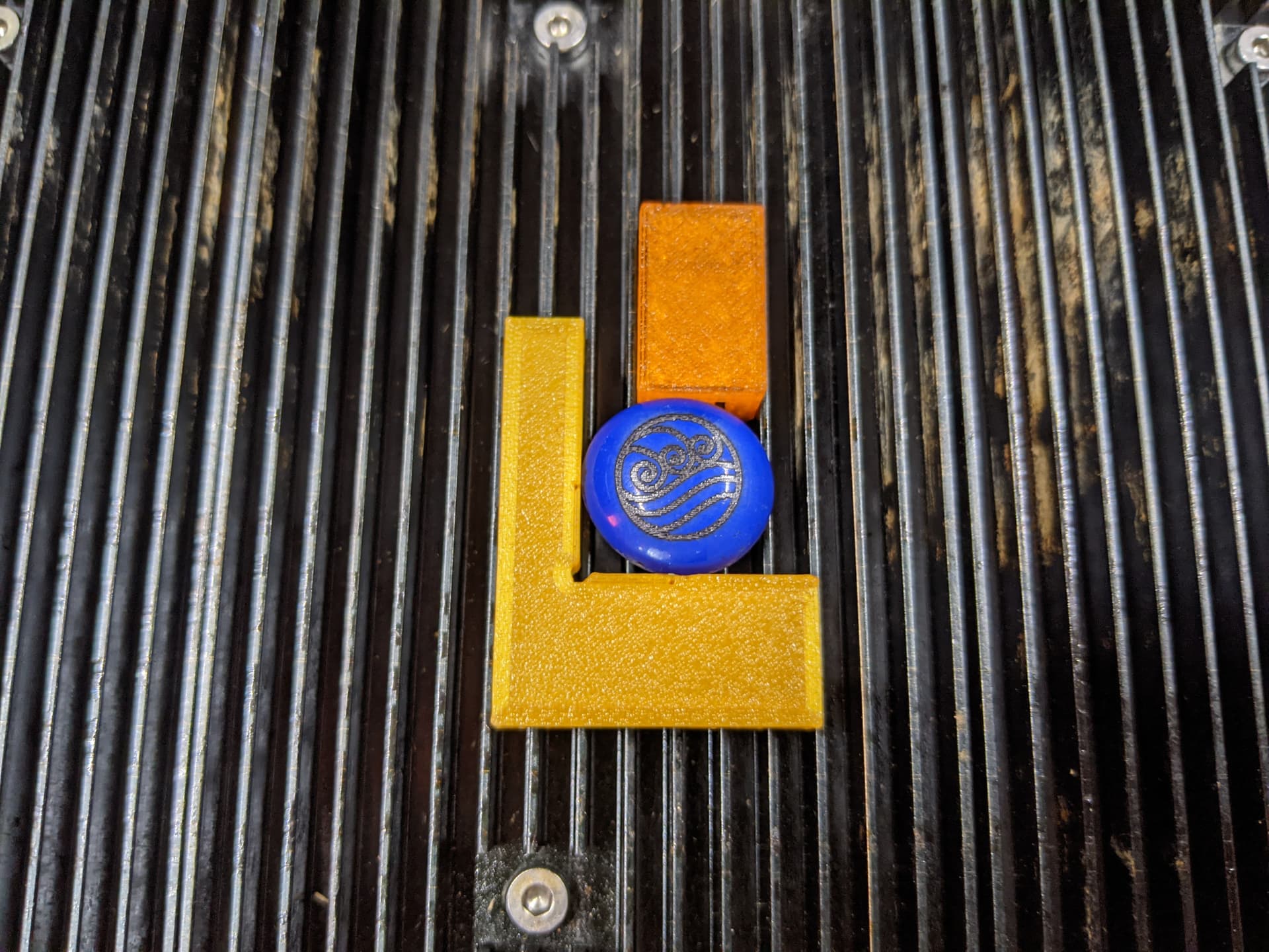
Finally got around to testing some glass! Wife was using these cheap glass “gems” to add weight to her crochet projects, and some of them were painted on the top vs the bottom, so I decided to finally test on glass. First one, naturally as seen, is on dark blue. Didn’t expect to work as well as it did (given the laser is blue). 500mm/min, 0.2mm interval (a bit rough for the 10W).

Second one was a very light blue, no picture of the original colour, but I washed it with acetone afterwards. This one was done at 0.15mm interval, can likely still go slightly finer.


Got my 10w and worked really good right out of box. rotary tool, engraved black anodized aluminum, from never using one to using rotary and anodized aluminum in less than 2 hours for me.
I do wish the rotary though would do actual 4-axis movement so on tapered objects or better yet instead of just entering a diameter, enter an actual 3D stl of an object. No reason it shouldn’t be able to move on all 4 axises during a lasher beam show.


Wow, is all I can say. Snapmaker and the 10W laser and no wishes remain open.
The calibration function absolute top, the thickness measurement of the material as well. I am fascinated.
Once calibrated, it goes through 4mm plywood like butter, but drive 2 times and only with 80% power, but usually it is already after the 1st round through absolutely top.
I’ve had it since 14.04.2022 and this is the first object I’ve lasered.


I am just totally thrilled with the 10W laser.
Something completely different than my old Neje laser or lasers from other manufacturers, the 10W laser works perfectly and with the camera and the material strength measurements it saves a lot of time.
A big praise to Snapmaker!!

Just got my 10w hooked up over the weekend, and am trying to print out some QR codes on anodized aluminum. Not sure if the stuff I got just had a quick bath or what (I can tell for sure it’s anodizing not some paint/coating) but I am BLASTING the stuff off at 100% power even at 500+mm/s.
When using the vector engrave (“on the line” setting) I do see that the laser dot size (0.05*0.2mm) is apparent. X-axis oriented lines and thin and crisp, Y-axis lines are… maybe a tad bold. It’s not a big deal, but it’s noticeable if you’re looking for it.
I was actually really hoping to take advantage of that when filling out all the white in the QR code by setting the fill mode to vertical lines during that portion, but apparently no matter what fill mode I set it to, the preview only shows the default horizontal lines. I’ve got the latest firmware and luban update.
The other (and honestly more irksome) problem I’m having is a weird one with spacing or… alignment? In the images you can see that the outer edged of the fill mode sections are all neat and in a line, but the inner sections seem to consist of lines that are set alternatingly left and right of each other.

The QR is a high res (20px per little square) jpg interpreted in Vector mode (Invert, Threshold 128, Impurity Size 2). The print settings are (an admittedly insane) 1000mm/s work and jog (to minimize wobble) at 100% power, using a line spacing of .125mm because that math’d out to make each dot of the code a consistent 4 lines high.

When I open the .nc file it all looks aligned like it should.

These were SVG graphics I made myself in inkscape to just test a pattern of little boxes with varying levels of line spacing (“Fill Interval” of 0.16mm default at the top left, dropping 0.01mm each step down to the bottom right) and you can see the same symptoms here. The bottom strips are just Luban rectangles told to fill with the same ranges, but for some reason the default 0.16 didn’t print, so they run 0.10-0.15mm, left to right. Print settings were (a much more tame) 400mm/s at 50%.
The big problem are those dang jagged edges. I barely managed to get the QR to scan, which, granted, at the size and level of complexity it’s at I know that’s asking a lot, but at the moment that’s just a design constraint. It did scan though! I just had to use an actual QR code app, and get it about at minimum distance before the camera went out of focus.
Here’s some photos I took of my first speed/power test on a light blue anodized aluminum plate. These are all ran at the default settings (like 0.16mm fill interval) except as noted. The blocky ovals are luban circles stretched out (8x4mm) and run as “on the line” vector engravings, the rectangles (4x2.5mm) are fill tests.
Here’s the files in case you find the hours I spend manually setting each parameter worth skipping XD
Laser Power Test.zip (115.9 KB)
(for reasons the origin is centered under the 300mm/s at 20% sample swatch. The Run Boarder works fine though, so just use that.)

As you can see though, this thing SLAPS out them photons.

My only precision ruler is in inches, forgive me. At least I’m using the decimal side, right?
These were taken under my microscope, and it was the weird spacing I saw that led my to try the Fill Interval tests in my previous post, above.


I think I’m seeing the same problem I was having with the uneven edges on the sides of your bee there, but I can’t be sure. Would you confirm that for me?
These last couple posts. “Laser inline power” sounds in the distance… lol
Yes, these are artifacts from some defects in the motion control algorithms and you’re seeing the acceleration and deceleration of the machine with constant power. Can read all about what may be in the near future here: Feature: Add Laser Inline Power control by brent113 · Pull Request #153 · Snapmaker/Snapmaker2-Controller · GitHub
Also, there are confounding separate motion control issues at play here too related to linear approximation and kerf and other things. Also you might have a slight wobble on your X axis causing some of final pictures. Also you have some slight backlash.
Lightburn can account for all of things properly, you should consider trying it.
Lightburn is certainly under consideration - do we need the DSP license to run the marlin in our controllers?
And thanks for the link, reading ahoy! I did notice some small X axis wobble in the Y direction when it reversed direction for the fill lines, that was part of why I though setting work and jog to the same speed might help things. Gonna go figure out how to do backlash compensation now too lol.
Backlash compensation would like like M425 X0.02 Y0.02 Z0.02 at the top of the gcode file, or in the lightburn header gcode section to be automatically added, as long as your backlash meets factory spec. If you’re measuring more than about 0.05 I’d recommend tightening the rails as this leads to long running positional error (more on that here):
You don’t need the DSP license.
For laser inline power currently it’s only working OK with the 10W laser and it isn’t publicly available yet, you’d have to compile from source from github so there will still be jitter, but I think it won’t matter much for what you’re doing at the moment.
To test backlash I’d do something like this: A350 - Not printing perfect circles - #25 by brent113. Generate a file with circles, before each circle int eh gcode file insert a new backlash. Here I did .1, .15, .2, and .25mm.
For any more you should probably start a new topic and reference this as this isn’t really anymore about the 10W laser, this is now talking about machine calibration.