Here is another project:

https://makerworld.com/de/models/2100838-snapmaker-u1-cover#profileId-2271872
Here is another project:
https://makerworld.com/de/models/2100838-snapmaker-u1-cover#profileId-2271872
Ufff, mine arrives in February… I’m really looking forward to seeing how you make that cover… I like the design and the idea that you don’t have to remove the entire cover for maintenance, that’s why I didn’t buy the original cover… because it would get in the way when removing it.
It looks very good. How will you cut the polycarbonate/glass into that shape?
Acrylic requires a carbon laser, but the other issue is the size of the laser bed, which is quite limiting.
If possible, keep the pieces small; it’s always a good idea.
Okay, I’ll finish testing the first version first, then consider reducing the size of the side transparent panels later.
If you buy from Taobao, you can ask them to process it for you.
It is believed that, when viewed from the front, narrowing the left side inward is unnecessary; when viewed from below, a straight line top to bottom is sufficient. This makes the PC board more square and provides more internal space. Reducing the top size offers no benefits other than aesthetics, and internal tubes will still connect to the cover.
Reducing the chamber size is considered for several reasons:
Besides, the current three PC panels are kept as square as possible, but overseas machining isn’t as convenient as in China, so I’ll offer two versions (a reduced side-door version and the current one).
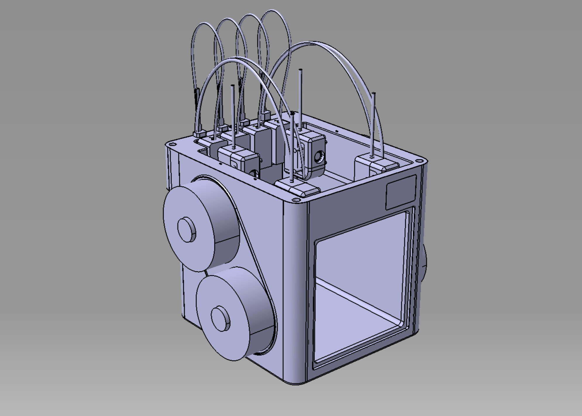
![]() In addition, I simulated the tube’s movement path, and it 100% won’t touch the top cover.
In addition, I simulated the tube’s movement path, and it 100% won’t touch the top cover.
The excess square part is replaced with a printout.
Although it’s easier to machine, it doesn’t look good.
I found a cheaper storage box then the IKEA one.
I also designed a frame holder for the box, only need 280g filament to print.
Feel free to explore it: https://makerworld.com/en/models/2126701
I don’t mean this in a bad way the cover reminds me of the cab to a forklift. Nice design looks good.
![]() Now that you mention it, I think it looks like it too!
Now that you mention it, I think it looks like it too!
Here is the final version appearance effect that has been tested so far.
This version uses magnetic door closure; apply a 1 mm-thick, 10 mm-wide strip of EVA tape to the frame. Here is 3MF:U1 TOP_COVER_for SMOrca.zip (3.4 MB)(2026-01-01)
Top Part STP:You can modify the STP file yourself.
Top part.zip (512.6 KB)
Door CAD :PC_Door_3pcs_CNC_3.17mm.zip (83.3 KB)
Latest machine STP file with adjusted dimensions:
Product_TOP_COVER_2025_1227.zip (671.1 KB)
DXF file for CNC or Laser Cut:
Here is final result photo:
Ventilation duct size:4inchs x 5cm
BOM Description,Note: use fast-drying glue to secure the magnets.
————————————————————————————————
PS:I will update later when I have time: LED light installation (mounting points already reserved), small-size panel drawings, and a recommended installation tutorial.
Nice work looks really good. The little dragon peaking over the back was a nice touch.
Wait, did you use PLA to print the main body? How will it handle heat?
Yes, I printed the main body directly with PLA, and the panels are PC sheets. As long as the chamber temperature stays below 50°C, I think it’s fine—most of the time I don’t print materials that need special insulation. So regular PLA/PETG/TPU is already enough. I’ll add a small thermometer to monitor it later.
The side and front doors are magnetically attached and can be opened directly. I’ve also reserved a vent on top that can be opened manually or later modified with a fan and filter.
Since my machine’s back is close to the wall, I didn’t consider adding filtration or fans there, as it would protrude too much. However, the back piece is 3D-printed, so mounting holes can be updated anytime—let’s discuss if it’s needed.
The side doors have an angled design; fans and filters can actually be mounted on the PC panels by simply adding four mounting holes in the CAD for DIY modification.