Hello! I’m Nick (nsclemmer here and mechcandphysics on Reddit and Twitter), and I’ve been getting quite a few questions recently about how I use the Bondtech LGX extruder with the Snapmaker 2.0 platform. I’ve been hesitant to post anything because I still consider this a work in progress, but I haven’t made any serious improvements in the last year or so. Considering the lack of changes combined with the release of the “vibration compensation” firmware for the 2.0, it’s a good time to get this information out there. Before I begin, I’d like to thank all the people in all the different forums that helped me better understand my machine, and how to make it work. Lots of the things that are listed here are things I’ve learned from other Snapmaker users, so thank you all. Let’s get started!
This mod in action: https://twitter.com/MechAndPhysics/status/1627684254368022528
Firstly, what is this mod? Simply put, this removes the 90% of the Snapmaker 2.0 printing module and replaces the extruder with a Bondtech LGX, the hotend with one of the Slice Engineering hotends, the bed level sensor with a Duet 3D IR sensor, and the 20mm part cooling fan with a 5015 blower fan.
Why should you spend the time and money on this mod?
-
Bondtech extruders and drive gears are known in the industry as one of the absolute best, and the LGX is their latest extruder and packs a serious punch when it comes to filament grip.
-
Slice Engineering hotends are also known to have some of the best thermal performance. With little to no heat creep and very little clogging, this is a fantastic brand for an all metal hotend.
-
These specific components are designed to work together because of their design partnership, and in doing so, the filament path from extruder gear to the end of the nozzle is one of the shortest in the business meaning almost no chance of the flexible filaments clogging as well.
-
The Duet IR sensor allows the Snapmaker to auto level on glass and has much higher precision when leveling on any surface.
-
Using a 5015 blower provides ample air flow and better part cooling when compared to the 20mm fan that comes with the Snapmaker printhead.
The main draw to doing this is drastic improvement in print quality/speed, the extruder is less prone to clogging, it prevents extruder issues like worn drive gears, improves bed leveling accuracy, and gives enough cooling performance to print PLA at high speeds. You’ll see a drastic increase in extrusion flow consistency, ability to print flexible materials, and it will print higher temperature materials without damaging the PTFE liner in the Snapmaker 2.0’s original print module. The volumetric flow rate of filament can get as high as 26mm^3/s with the Mosquito hotend and a 0.6mm nozzle. In all, it makes the Snapmaker a formidable printer.
What will you need?
-
Any Snapmaker 2.0 machine, but it’s preferable to have a “T” model or the upgraded linear rails to get the most out of the higher flow rate and the new firmware. Snapmaker 2.0 Modular 3-in-1 3D Printer A350T/A250T | 3D Printer Models – Snapmaker US You’ll also want to grab an extra 3D printing module because you will need to pillage the board, the heater, and the thermistor. Snapmaker 3D Printing Module – Snapmaker US
-
A Bondtech LGX (not the lite version) Bondtech LGX Large Gears eXtruder is smarter, smaller, lighter, and a heatsink Heatsink - Bondtech
-
One of 7(!) Slice Engineering hotends. You can choose between:
a. Any of the three LGX Ace hotends Bondtech LGX ACE Hotend Attachment | Slice Engineering
b. The Mosquito Magnum+ (air cooled) Mosquito Magnum+ Hotend: Build & Order | Slice Engineering
c. The Mosquito Magnum Slice Engineering Mosquito Magnum Hotend Kit for Sale
d. The Mosquito The Mosquito® 3D Printer Hotend | Slice Engineering
e. The Copperhead Slice Engineering Copperhead Hotend for 3D Printing.
Tip 1: If you get one of the non-Ace versions, you’ll need this aluminum interface adapter LGX® Anodized Aluminum Interface Plug for Direct Extruder Applications and this 24V hotend fan from Slice Hotend Cooling Fan for Mosquito® & Copperhead™ | Slice Engineering.
Tip 2: If you get one of the Ace versions, you’ll need a 40mm fan like this one https://www.amazon.com/gp/product/B07L3CT33J/ref=ppx_yo_dt_b_search_asin_title?ie=UTF8&psc=1.
Tip 3: I personally recommend using the Ace hotends because it’s the shortest filament path and still has excellent cooling, but if you already have the full size versions, I made sure the adapter plate fits the non-Ace versions.
Tip 4: This mod does NOT work with the LGX Shortcut (the predecessor to the Ace).
Tip 5: It should be known that without some serious modification, you cannot use both heating tubes on the Slice Engineering Mosquito Magnum+ (I have done this, but I will not go into detail on it because it neglects any thermal runaway protection).
Tip 6: My recommendation for general use is the Ace Mosquito, and it’s what’s shown in most of my videos/photos/CAD (though I have used all of them for testing purposes). -
A decent Rip-Rap nozzle (possibly many!). Bondtech CHT BiMetal Coated Nozzle For RepRap M6 Heat Blocks
-
A Duet 3D IR bed level sensor. Duet 3D
-
Any 24V 5015 fan. https://www.amazon.com/gp/product/B07DB7DLMM/ref=ppx_yo_dt_b_asin_title_o02_s00?ie=UTF8&psc=1
-
Tools including:
a. Crimper https://www.amazon.com/gp/product/B019ARWWFY/ref=ppx_yo_dt_b_asin_title_o02_s00?ie=UTF8&psc=1
b. Wire stripper https://www.amazon.com/gp/product/B08W44T2XJ/ref=ppx_yo_dt_b_asin_title_o08_s01?ie=UTF8&psc=1
c. Decent flush cutters https://www.amazon.com/gp/product/B000GTMZHG/ref=ppx_yo_dt_b_search_asin_title?ie=UTF8&psc=1
d. Misc. tools such as needle nose pliers, hex keys, screwdrivers, and calipers. -
Braided sleeving https://www.amazon.com/gp/product/B074GN12PY/ref=ppx_yo_dt_b_asin_title_o08_s01?ie=UTF8&psc=1 and heat shrink https://www.amazon.com/gp/product/B084GDLSCK/ref=ppx_yo_dt_b_asin_title_o08_s01?ie=UTF8&psc=1.
-
24 or 26 awg wire https://www.amazon.com/gp/product/B07TJZ9XRR/ref=ppx_yo_dt_b_asin_title_o02_s00?ie=UTF8&psc=1 (this is not great wire, but it has a lot of colors).
-
Connectors for the:
a. Fans https://www.amazon.com/gp/product/B015Y6JOUG/ref=ppx_yo_dt_b_asin_title_o07_s00?ie=UTF8&psc=1
b. Stepper motor https://www.amazon.com/gp/product/B07L3GL995/ref=ppx_yo_dt_b_asin_title_o02_s00?ie=UTF8&psc=1
c. Bed level sensor (board side) https://www.amazon.com/gp/product/B07D241T3M/ref=ppx_yo_dt_b_asin_title_o01_s00?ie=UTF8&psc=1.
d. Bed level sensor (sensor side) https://www.amazon.com/gp/product/B07DF9BJKH/ref=ppx_yo_dt_b_search_asin_title?ie=UTF8&psc=1 -
Hardware (get extra)
a. Zip ties https://www.amazon.com/gp/product/B07VBWK773/ref=ppx_yo_dt_b_asin_title_o00_s00?ie=UTF8&th=1
b. (2) M2x3.2x3 Heat Set Inserts https://www.aliexpress.us/item/2255800046211358.html?spm=a2g0o.store_pc_groupList.8148356.20.fe902481OggbHs&pdp_npi=2%40dis!USD!US%20%244.00!US%20%243.00!!!!!%402101f49d16770335355811213eb32f!10000000944761262!sh&gatewayAdapt=glo2usa&_randl_shipto=US
c. (3) M3x5x3 Heat Set Inserts https://www.aliexpress.us/item/2255800046543591.html?spm=a2g0o.order_detail.order_detail_item.19.2363f19cC0goG5&gatewayAdapt=glo2usa&_randl_shipto=US
d. (6) M3x5x6 Heat Set Inserts https://www.aliexpress.us/item/2255800046543591.html?spm=a2g0o.order_detail.order_detail_item.19.2363f19cC0goG5&gatewayAdapt=glo2usa&_randl_shipto=US
e. (4) M4x6x6 Heat Set Inserts https://www.aliexpress.us/item/2255800046610840.html?spm=a2g0o.store_pc_groupList.8148356.29.fe902481OggbHs&pdp_npi=2%40dis!USD!US%20%243.50!US%20%242.62!!!!!%402101f49d16770335355811213eb32f!12000022829623997!sh&gatewayAdapt=glo2usa&_randl_shipto=US
f. (2) M2x8 Low Profile Socket Head Screws McMaster-Carr
g. (2) M2x10 Low Profile Socket Head Screws McMaster-Carr
h. (2) M3x4 Low Profile Socket Head Screws McMaster-Carr
i. (7) M3x6 Low Profile Socket Head Screws McMaster-Carr
j. (2) M3x8 Low Profile Socket Head Screws McMaster-Carr
k. (2) M3x14 Low Profile Socket Head Screws McMaster-Carr
l. (1) M3x20 Low Profile Socket Head Screw McMaster-Carr
m. (3) M3x25 Low Profile Socket Head Screw McMaster-Carr
n. (2) M2 Hex Nuts McMaster-Carr
o. (2) M2x2 Plastic Spacers McMaster-Carr (this is for an M2.5 screw, but it will work) -
(2) 1N4148 diodes as described by brent113 in this post 3DP Part Cooling Fan 5015 Replacement
-
The resistors and transistor listed by stewl on this post For all who want level on glass - #159 by stewl
-
Lastly you’ll need to print these parts: Printables. Please choose only 1 fan shroud based on the hotend you picked in an earlier step. These will need to be printed in ABS. I have a file of the adapter plate that can be simply milled from a 6mm sheet of aluminum, but I didn’t publish that. If Snapmaker wanted to make an upgrade kit, I’d share it with them (hint hint).
Now that you have all your pieces, it’s time to put this together! I’ll try to take my time with these steps, and errors can result in fried 3D printing boards, burnt fingers, and an overall bad time (I know firsthand).
-
Print the aforementioned parts in ABS if possible. Use high strength settings such as the ones recommended by Voron here: Sourcing Information | Voron Documentation, or print them solid. Use only the fan shroud for your hotend. The in progress part of this is the run-out sensor which I don’t currently use, so it may be wise to avoid printing that at the moment as it’s not great. Don’t use low temperature plastic like PLA as it will warp and this is especially devastating for the fan shroud (I also know this from experience).
-
Put the heat sets in the:
a. Adapter plate - (4) M3x5x6 and (4) M4x6x6
b. Fan Mounting Plate - (2) M3x5x6 and (3) M3x5x3
c. Filament Run-out Sensor Plate - (2) M2x3.2x3
d. Clean up any excess plastic so the threads are accessible from both sides. -
Assemble the Slice Engineering hotend you picked following the instructions provided with the hotend. Use the heater and thermistor from the Snapmaker 3D printing module, and make sure the wires are coming out the proper side of the hotend. Do not install any fans yet.
-
Assemble the Bondtech LGX to the Slice hotend following the instructions provided with the hotend. This is also the best time to stick the heatsink to the back of the LGX stepper motor. It’s not shown in any of the CAD, but it needs to be here.
-
Attach the filament run out sensor to the run out sensor plate using (2) M2x10 screws. (optional step)
-
Attach the filament run out plate to the fan mounting plate using (2) M3x4 screws. (optional step)
-
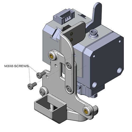
Attach the fan shroud to the fan mounting plate using (1) M3x6 screw.
-
Assemble the fan mounting plate and the Bondtech extruder using (2) M3x6 screws.
-
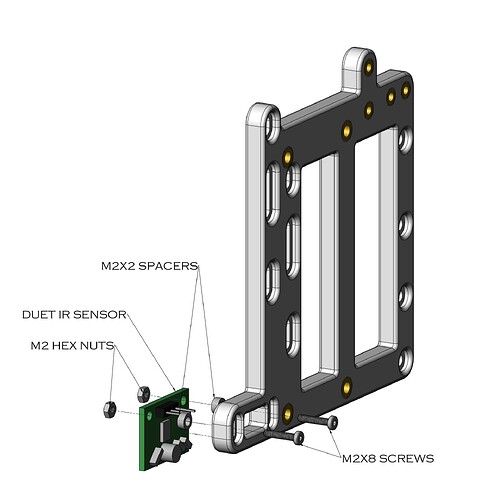
Attach the Duet IR sensor to the adapter plate using (2) M2x8 screws, (2) M2 hex nuts, and (2) M2x2 spacers. Remember to put the spacers in between the adapter plate and the IR sensor. Make sure the IR sensor is 8mm below the bottom of the adapter plate.
-
Combine the Bondtech extruder and the adapter plate using (2) M3x8 screws. Make sure the nozzle is 9mm below the bottom of the adapter plate. Use the correct holes for the hotend you chose based on the photo below.
-
At this point, it’s time to make/remake some wiring. Unfortunately, I studied mechanical engineering and not electrical, so please feel free to make adjustments as needed.
Note that the wires will all need to lead to 3D printing board shown below, so cut wire lengths carefully. It may be worth jumping a few steps ahead to dry fit the fans, IR sensor, and 3D print board in order to get the cut length correct. I have all mine cut at about 150mm which is intentionally very long. Please use the cable sleeve and heat shrink on the cables when you’re confident in your length.
a. Cut the part cooling fan wire to length. Re-crimp the cable ends using the JST-XHP connector and pins. Make sure to put a diode into the JST-XHP pins before you crimp it, and that it’s in the correct orientation. Be sure to check the red and black wires are in the correct sides of the connector, as Snapmaker is opposite (red and black swapped) of most fans.
b. Repeat step “11a” with the hotend fan.
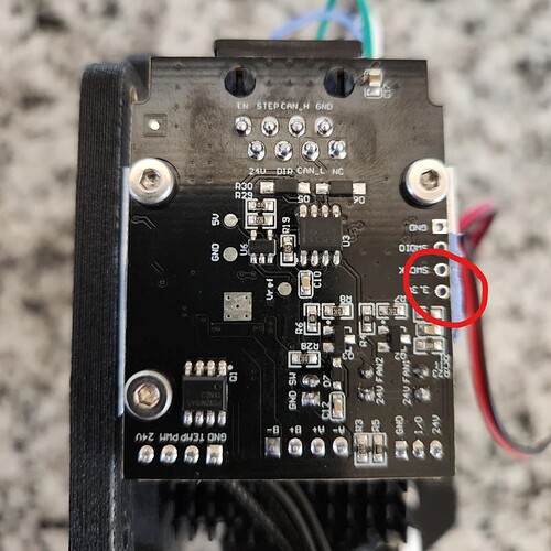
c. Next is the most challenging cable because you’ll need solder a wire to the 3.3V port of the Snapmaker’s 3D print board. Make sure it’s coming out the back side and does not interfere with the aluminum mounting bracket on the front. Follow stewl’s guide from earlier to make the wire (with the resistors and transistor), and use the 3 pin Dupont connector on the side for the for the IR sensor, and the 3 pin JST-PHR connector for the 3D print board side. I don’t have this shown on any working 3D print boards because I have plans to make an adapter PCB board so no soldering is involved.
d. Lastly, we need to make the stepper motor cable. Use a 6 pin JST-PHR connector for the motor side and a 4 pin JST-XHP for the 3D print board side. Follow the photos below for the correct wiring of the connectors.
-
Add the part cooling fan to the assembly using (1) M3x25 and (1) M3x20 screws.
-
Add the hotend cooling fan to the assembly. Use the provided screws if using the Slice fan, use (2) M3x25 screws for the 40mm x 20mm fan, or M3x14 screws for the 40mm x 10mm fan.
-
Attach the 3D print board to the adapter plate using (2) M3x6 screws.
-
Carefully wire all the components to the 3D print board. Reference the diagram in step 11 to make sure you have the wires in the correct spot. Put the 2 fans and the IR sensor through the zip tie, but do not tighten it yet.
-
Attach your new print module to the Snapmaker X-axis using (4) M4x8 screws. Note that the location of the holes in the X-axis are different than the stock print module.
-
Make sure the IR sensor cable is looped around the side and up to the zip tie with no slack that can have it touch the bed. Once this is the case, tighten the zip tie.
-
Here’s where it gets less formal. I recommend gluing a bowden tube to the filament runout sensor plate just above the switch. This way the filament will trigger the switch when it comes out the tube. This is imperfect, and I will make something better I promise!
-
Rejoice! You’ve assembled the the new print head!
The last thing you’ll need to do to begin printing is calibrate the extruder as shown in this post by sdj544 Summary: Extruder calibration a must. 400 is a good starting point for the value, but I use 416.7 right now. Also, please update any slicing profiles with the appropriate retraction speed that Bondtech recommends. It would be wise to run a few calibration prints to make sure your settings are good with this upgrade.
The beauty of this mod is it requires no firmware changes. The nozzle, and the bed level sensor are in the exact same spot as before, so you don’t have to overwrite any firmware. There are some things that would benefit from firmware changes, and I’ll go into those below.
-
The amperage delivered to the Bondtech LGX is higher than what’s recommended by Bondtech, and that would require a firmware change to fix. The good news is the heatsink helps, and I’ve had no problems in the 1.5 years I’ve been using this mod.
-
Unfortunately, you will still be limited to the 275C that is present on single extrusion module unless you edit the firmware. This is something you’ll have to do on your own as it can be damaging to the machine. I would also recommend an industrial 40W heater (from E3D) and a 300C thermistor (from Slice) if you choose to do that.
One big note, is for people like me who don’t mind manually leveling until there is a plug in adapter for the IR sensor, you’ll need to do the initial calibration with the original printhead that the board came from before doing this mod. If you skip this, the machine will try to auto level and the printhead will plunge into the build plate.
I’d like to end this with some future upgrades that I already have planned.
-
A cable chain setup. The M3x5x6 heat sets in the adapter plate line up with IGUS and generic cable chains. I am using them currently, but it requires cutting and lengthening the tool head cable, so I didn’t add that to the assembly instructions.
-
PCB adapter plate for the Duet IR sensor. I am already working on a 24V to 3.3V plate that includes all the necessary resistors and transistors to operate the IR sensor from the original bed level sensor port. The 2 holes in the bottom of the adapter plate below the 3D print board will hold the new PCB board.
-
Fixing the filament run out sensor plate. This hasn’t been the top of my priority list because I don’t use it enough. I did have one scare with TPU, so I’ll get working on it soon.
That’s it. That’s the whole mod. I hope you have fun making it your own, or just appreciating it if you don’t want to go through the trouble. Please ask any questions, and post any remixes of this you have here so I can keep it updated with you.
Thanks for taking the time to read this! Have a good day!
~Nick


