Some time ago a need arose to print some car parts with ASA, knowing about problems with PTFE Liner that high temperature can cause I set a goal to introduce some modifications to the print head in order to
- Achieve safe prints at temps >260°C
- Make it print faster
- Do it cheap, if works, try better components
DISCLAIMER
Hardware - A350T, stock latest print head design. Enclosed.
Software - PrusaSlicer, latest alpha.
I intentionally disregarded the “change one thing at a time” principle, just to make it more fun and waste more time. Because why not ![]()
So don’t expect this to be a CNC Kitchen level science experiment. I’m no FDM guru with 15 years of scientific research. I went for quick and dirty way to increase my reliable production volume with acceptable (not perfect) print quality.
Almost all pics are under spoilers.
Solution for safe prints at temps >260°C
Based on shared knowledge
- Hot End Clogs - The How & Why - thanks @Mxbrnr
- FYI: Snapmaker 2 All-Metal Hotend Simple Mod - thanks @Franky
- And follow post - FYI: Snapmaker 2 All-Metal Hotend Simple Mod - #63 by Franky
I’ve come up with couple places that need attention
- Cancel PTFE insert = replace stock heatbreak with Bi-Metal Heatbreak.
- Cancel heatcreep = see above and sprinkle some improved airflow around heatsink
Solution for Make it print faster
After watching following videos
- https://youtu.be/20K4d8jLTq8 - by Stefan
- https://youtu.be/WgXM2zPusXo - by Thomas Sanladerer
obvious solution seems to be CHT Nozzle X 0.6 Nozzle diameter = I blinked and it printed benchy
- It didn’t ![]()
Solution for Do it cheap
Well, Aliexpress is my friend here. Cut corners, skip steps and all that will come handy and bite me in the ass too.
Let’s mod
Shopping list
Prices accurate at the moment of writing the post.
- Heatbreak $4.88 (for 1pc) - I purchased “Cu-Ti” from RAMPS - pick correct option.
- Turns out our stock heatbreak is very close relative to standard CR6-SE heatbreak. The one I purchased turned out to be legit. At least on the copper side. I tried grinding the Ti part to see white sparks, but my dremel grinding bit isn’t good for it. See pics below.
- PTFE insert $3.49 (for 1m with coupler) - can’t be canceled 100% here, but you need MUCH less of it and miles away from heat block. See pics below.
- MK8 0.6mm CHT nozzle $4.77 (for 3pcs) - good reviews and +1000 sold units convinced me about this. Bronze with copper insert. Verify the insert is the right side up, just in case.
- Fan for improving airflow $0 (for 0 pcs) - I’ve decided against buying recommended by @Franky fan. I had a feeling that something can be done without replacing the stock fun. This turned out to be true and saved me some time and money.
- Thermal paste $5.47 (for 4gr) - I had some Arctic MX-4 laying around. I know Thermal Grizzly is all the rage this days, MNF claims it is stable at +350°C. But it costs ~$3.2 per gramm (5.55gr package) vs ~$1.35 per gramm (4gr package) for Arctic MX-4. We are keeping it cheap here and not trying to get >70°C at the heat sink. So Arctic MX-4 with it’s upper limit of +150°C is perfect for application. Also no need to increase thermal interface efficiency if there is now way to increase heat removal from the heatsink.


Two weeks later…
Assembly - Exercise caution - it is HOT, easy to damage
Tools & supplies needed
- All of the above
- 6mm socket
- 7mm socket
- Adjustable wrench
- Pliers (can replace the sockets)
- Very sharp and very thin blade
- Small side cutters
- Snapmaker screwdriver
- Cloth / paper towel to clean up.
If you never replaced a hotend - read this article & watch this video first.
I modded a brand new hotend. With machine off, I plugged in new hotend and turned it on. Heated up the hotend to 260°C. With adjustable wrench holding heat block, heatbreak came out easy with pliers. Then 6mm socket to unscrew the nozzle. Then 7mm socket to put in new nozzle, and gentle use of pliers to attach the new heatbreak. No need to make it super tight. Just make it snug and firm. Let it cool Turn off the machine and let it cool down.

Take the print head off to a work bench.
- Prep PTFE insert - Cut 4.5mm of PTFE tube for insert. Don’t use side cutters for this. How to cut PTFE tube. Make sure it is flush with the heatbreak rim. Gaps are bad.
- Now to airflow issue - looking at the internals of the head, it seems like nobody thought of a good airflow. You can tell that goal was to make it pretty outside and cramp everything inside no matter what. Intake is ok more or less, but exhaust is almost non existent. Turning off part cooling fan doesn’t mean you stop air from blowing at your print. The heatsink fan will be on no matter what if nozzle temp >=60°C. air being a fluid will try to find easiest way to escape, and it is through the gaps to the part printing. This tripped me up later. Heavily restricted exhaust not allowing air to get in, putting a bigger/faster fan will not do much in my humble opinion. Reason I went with stock fan.
- Start with vents. Fan side = intake. Opposite side exhaust. Dust covers are pretty restrictive, I’d say 40-50% of surface area is closed. So I removed some of it, but not all of it. With sharp and thin blade - slice the material above the rib and then pry of the metal. This is reversible.

- The fan duct (little piece of plastic under fun with leveling probe attached to it). Some taking apart is required to get to it.
- Two screws on the back to make the part cooling duct loose.
- Two screws along the side to remove the fun. Watch the wires - don’t cut them on sharp edges.
- Finally probe with duct. The duct has little lip that just covers some of the heatsink fins. No good, cut it off with side cutters.


Now put everything back together. Apply some grease (not a lot) to the heat break, stick in the PTFE insert, slide it in and secure with set screw. Double check the wires are not shorted / pinched. Pay attention to fan wires.
The leveling probe will have to be readjusted. I had to slide it all the way down in my case. The new nozzle sticks out more then the stock nozzle.

The mod is complete. Put the head back to adjust the leveling probe. I had to slide the head down on the bracket, in order to access the adjustment screw. Then mount it the right way to do auto leveling.
I’ve attached thermocouple between the fins, made sure to lube it with thermal paste and secure it nicely to the metal. But covered from the oncoming air. Toothpicks everywhere ![]()
Off to testing / printing
Heating nozzle up to 270°C for 4 hours showed heatsink temp at stable 56°C no more. Good. Not for PLA but awesome for ASA/ABS.
Following 3D Printer Line/Extrusion Width | Best Settings & Examples & Creating profiles for different nozzles I made up test profiles. And straight to printing, failing miserably. My layer adhesion almost non existed with ASA by 3dxTech. Issues with drive grinding the filament away before it was able to push/retract. Closed the gaps between nozzle and head body with some HVAC tape leaving the part cooling fan duct open. Test run can feel the draft even with the part cooling fan off. Closed it too.
Results got match better with layer adhesion. But not ideal.
PIC mockup of covered gaps
I had to remove the cover for PLA print, but here pic below will explain.

Gaps cover template.zip (1.1 KB)
After running a bunch of test with different parameters, I gave up on filament and switched to Polymaker ASA. And it came out almost ideal.
As for the grinding issue, it forced me to figure out if the volumetric flow capacity increased at all. So using the Determining Maximum Volumetric Flow Rate | Ellis’ Print Tuning Guide I got to testing. E-steps calibrated with @Mxbrnr writeup.
Volumetric Flow test method
Using table below and handy measuring guide made of a clear straw 100mm long with mm scale at the bottom (DIY). I would mark the filament with white sharpie at the top edge of the straw, and extrude the length, using bottom scale to count how much of it left over.
The tables below are all my calculations. Hope they are correct ![]()
From the specs our stock volumetric flow is 9mm³/s. But with what parameters and filament is a secret.
I would stop running the test once I saw a dropoff more then 1-2 mm unless something forced to me continue. Temperature for the first column is the temperature from the best layer of a temp towers I printed a while ago. Modded tests used this temp as start point.
| Filament Dia | 1.75 | mm |
|---|---|---|
| Filament Area | 2.41 | mm2 |
| Extrusion Length | 100 | mm |
| Stock Max Flow | 9 | mm³/s |
| Flow Rate (mm³/s) |
Feed Rate (mm/sec) | Feed Rate (mm/min) | G-code |
|---|---|---|---|
| 2mm³/s | 0.832 | 50 | G1 E100 F50 |
| 3mm³/s | 1.247 | 75 | G1 E100 F75 |
| 4mm³/s | 1.663 | 100 | G1 E100 F100 |
| 5mm³/s | 2.079 | 125 | G1 E100 F125 |
| 6mm³/s | 2.495 | 150 | G1 E100 F150 |
| 7mm³/s | 2.910 | 175 | G1 E100 F175 |
| 8mm³/s | 3.326 | 200 | G1 E100 F200 |
| 9mm³/s | 3.742 | 225 | G1 E100 F225 |
| 10mm³/s | 4.158 | 249 | G1 E100 F249 |
| 11mm³/s | 4.573 | 274 | G1 E100 F274 |
| 12mm³/s | 4.989 | 299 | G1 E100 F299 |
| 13mm³/s | 5.405 | 324 | G1 E100 F324 |
| 14mm³/s | 5.821 | 349 | G1 E100 F349 |
| 15mm³/s | 6.236 | 374 | G1 E100 F374 |
| 16mm³/s | 6.652 | 399 | G1 E100 F399 |
| 17mm³/s | 7.068 | 424 | G1 E100 F424 |
| 18mm³/s | 7.484 | 449 | G1 E100 F449 |
| 19mm³/s | 7.899 | 474 | G1 E100 F474 |
| 20mm³/s | 8.315 | 499 | G1 E100 F499 |
| 21mm³/s | 8.731 | 524 | G1 E100 F524 |
| 22mm³/s | 9.147 | 549 | G1 E100 F549 |
| 23mm³/s | 9.562 | 574 | G1 E100 F574 |
| 24mm³/s | 9.978 | 599 | G1 E100 F599 |
These are highly synthetic results and the real world printing will be a bit different / less.
Results
| Max Flow calibration - STOCK | ||||
|---|---|---|---|---|
| Stock 0.4 nozzle | ||||
| Stock heatbreak | ||||
| Filament | California PETG Fluorescent Orange | |||
| Density | 1.27g/cm3 | |||
| Leftover mm | ||||
| Feed rate/Temp | 235°C | 240°C | 245°C | 250°C |
| 150mm/min | 8.5 | |||
| 200mm/min | 9 | |||
| 225mm/min | 9 | 9 | ||
| 249mm/min | 9 | 9 | 9 | |
| 274mm/min | 10 | 10 | 10 | 10 |
| 299mm/min | 11 | 11 | 11 | |
| 349mm/min | 14 | 14 | ||
| Filament | Snapmaker PLA | |||
| Density | 1.24g/cm3 | |||
| Leftover mm | ||||
| Feed rate/Temp | 210°C | 215°C | ||
| 150mm/min | 4 | |||
| 200mm/min | 4 | |||
| 225mm/min | 4 | |||
| 249mm/min | 6 | |||
| 274mm/min | 9 | |||
| 299mm/min | 14 | 14 | ||
| 349mm/min | ||||
| Filament | Plymaker Polylite ASA | |||
| Density | 1.13g/cm3 | |||
| Leftover mm | ||||
| Feed rate/Temp | 250°C | 255°C | 260°C | |
| 150mm/min | 4 | |||
| 200mm/min | 5 | |||
| 225mm/min | 5 | |||
| 249mm/min | 5 | |||
| 274mm/min | 6 | |||
| 299mm/min | 7 | |||
| 349mm/min | 11 | 12 | 12 |
=======================
| Max Flow calibration - MODDED | |||||
|---|---|---|---|---|---|
| CHT 0.6 nozzle | |||||
| Bi-Metal heatbreak | |||||
| Filament | California PETG Fluorescent Orange | ||||
| Density | 1.27g/cm3 | ||||
| Leftover mm | |||||
| Feed rate/Temp | 235°C | 245°C | 250°C | 255°C | |
| 150mm/min | 6 | ||||
| 200mm/min | 6 | ||||
| 225mm/min | 7 | 6 | |||
| 249mm/min | 8 | 6 | |||
| 274mm/min | 9 | 9 | |||
| 299mm/min | 12 | 9 | |||
| 349mm/min | 18 | 15 | 13 | ||
| 399mm/min | 16 | 17 | |||
| 449mm/min | n/a | ||||
| Filament | Snapmaker PLA | ||||
| Density | 1.24g/cm3 | ||||
| Leftover mm | |||||
| Feed rate/Temp | 210°C | 220°C | 230°C | ||
| 150mm/min | 4 | ||||
| 200mm/min | 6 | ||||
| 225mm/min | 8 | 7 | |||
| 249mm/min | 12 | 8 | |||
| 274mm/min | 12 | 9 | |||
| 299mm/min | 11 | ||||
| 349mm/min | |||||
| Filament | Plymaker Polylite ASA | ||||
| Density | 1.13g/cm3 | ||||
| Leftover mm | |||||
| Feed rate/Temp | 250°C | 260°C | 270°C | ||
| 150mm/min | 3.5 | ||||
| 200mm/min | 4 | ||||
| 225mm/min | 5 | 4 | |||
| 249mm/min | 7 | 7 | 5 | ||
| 274mm/min | 10 | 11 | 7 | ||
| 299mm/min | 12 | 11 | 9 | ||
| 349mm/min | 16 | 16 | 15 |
Some notes on results. When testing I’ve noticed decreased volumetric flow with ASA for example. Didn’t make sense to me. But looking atthe temperatures while extruding I noticed a steady drop to 4-5°C below set temp. So my theory is that the heat block can’t keep up with CHT nozzle. It simply transfers heat faster to the filament then the heatblock can supply. So I increased the temperature, and got better results.
I could’ve done better job with measuring at consistent temperature steps, but I was rushing through this.
In the end I decided to use following numbers as a start for profiles in Prusa.
| Filament | California PETG Fluorescent Orange | ||||
|---|---|---|---|---|---|
| Feed rate | Leftover mm | Flow Rate (mm³/s) | TEMP | ||
| 299mm/min | 9 | 12mm³/s | 245°C |
| Filament | Snapmaker PLA | ||||
|---|---|---|---|---|---|
| Feed rate | Leftover mm | Flow Rate (mm³/s) | TEMP | ||
| 274mm/min | 9 | 11mm³/s | 230°C |
| Filament | Plymaker Polylite ASA | ||||
|---|---|---|---|---|---|
| Feed rate | Leftover mm | Flow Rate (mm³/s) | TEMP | ||
| 299mm/min | 9 | 12mm³/s | 245°C |
After dialing in the settings, I got way better results. But i’m fighting oozing ![]() Not a big deal on most of the prints I do.
Not a big deal on most of the prints I do.
Here is a couple of screenshots for PLA speed. along with print timelapse.

Closing thoughts
-
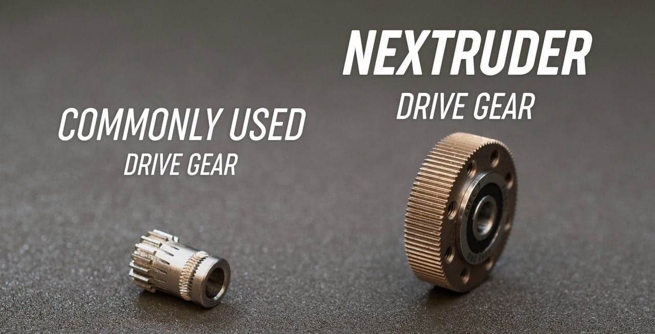
I think biggest roadblock is the diameter of the direct drive gear. It is too small to push the filament and not cut chunks out of it. It is way bigger at the dual extruder (hense the 22mm³/s max flow). But compare the dual extruder gear with with Prusa MK4…
-
Then goes the heat block, it needs more thermal mass to keep up with the CHT nozzle. Not sure if improving on thermal interface makes sense here (aka lube the threads with paste).
-
For ultimate fast extrude solution - The (mostly) Complete Guide to Bondtech, Slice, and the Snapmaker 2.0
-
I got what I needed, with few caveats, like oozing and very light stringing, this will be tuned out

-
this was a lot of text.
-
The timelapse above was printed using this project - PrusaSlicer_Project.zip (28.0 KB)