Thanks for the reply @Artezio, there’s no such thing as a late reply on here, no idea what timezone everyone is in 
I saw a post on Facebook where a user had made 6 toolpaths 60 degrees apart, indexing the machine between them to get around the limitations of the free version of Fusion360, is that the way you mean it can be done in Aspire? I also watched a video by Lex of DeskProto where he did most of the job using a wrapped toolpath and then created individual, indexed toolpaths to cope with areas needing undercutting, that was interesting.
I’m just trying a Linkage job from Luban on a ‘ball in a cage’ stl file from Thingiverse, looking good so far, I’ll report my findings here tomorrow when its finished. I know Luban is not really free, its part of the purchase but I don’t want to shell out more money unless I’m sure it will take me in the right direction. I thought I had enogh expensive hobbies with photography and electronics, seems like this one is just as bad. 
@albutch yes that’s very close. Create multiple toolpaths and modify the post processor to enable the identical functionality of it being a continuous rotary. Though for actual lathe machines where this would apply, chances are people would just use the software to utilize it. Vectric is working on officially adding continuous rotary support though. They also released laser support, it’s in its infancy though.
As far as hobbies… it’s never cheap lmao
Thanks, @albutch. I’m looking forward to hearing your results with the ball in a cage. If you get it working, I hope you will share your settings.
Will do. Here’s a quick video of the action. As you can see, the overall diameter of the bit isn’t accounted for as the bit moves down into the work. This means that material may be removed where it shouldn’t. Still some way to go before it gets to the ball - the really interesting bit. it might turn out square
.
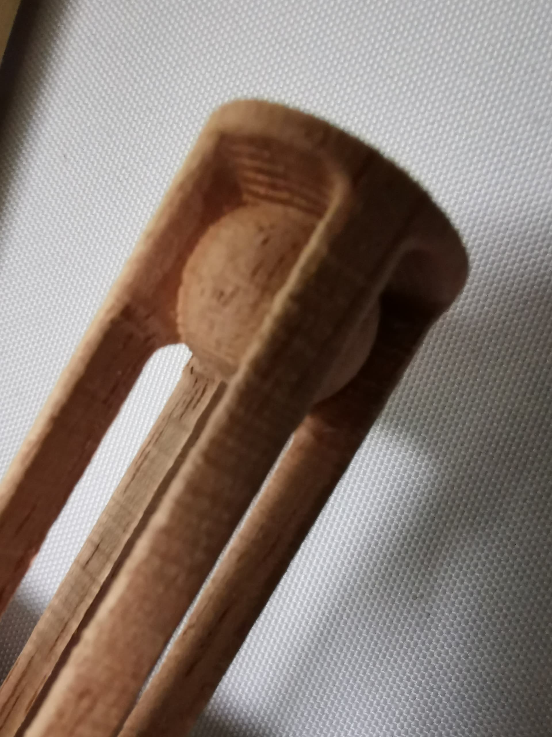
Close but not close enough, the ball is trapped.
I used the standard settings for the straight groove v-bit as supplied but changed the shaft dimension to 4mm to suit the bit I used. It does suggest that the toolpath created knows it cannot carve a gap less than the shaft diameter. I’ll design my own model with a bigger gap and try again.
It seems that the program does not make automatic tool compensation
I also found the same problem.
Agree with you!!
It looks like the rotary module simply screws down onto the CNC platform, rather than attaching to one of the linear modules. Would it be possible to use either of the rotary modules with the Snapmaker Original?
@JohnDoe117 no. It’s not even the same kind of connector, it would have no way of connecting up to the original. Even if it were, the firmware of the original doesn’t support it. Also, I don’t see why it would ever be attached to a linear module, there is no point in that method of attachment.
Yes, I noticed that the 2.0 model uses a different connector not long after I posted this question.
Given that there’s no possible way to use it with my SM, I’m trying to come up with a relatively cheap alternative to simply purchasing a 2.0 model and the rotary module.
I want to turn wooden knitting needles. They’re essentially just a long thin dowel with a tapering point on one end, but they’re of a very precise, consistent diameter. (2.5mm, 5mm, etc.)
For such a simple solid of revolution, I really only need a way to spin the workpiece at a consistent speed within the work envelope of the CNC module. I’m considering clamping the SM to the table on my drill press, laid on it’s side. Has anyone tried that or something similar? How tricky is it to align the drill’s axis of rotation with the tool’s y axis?
@JohnDoe117 what you’re needing is a lathe, the rotary module doesn’t spin at constant speed and it’s max speed is governed.