Hi folks,
for the first time I tried the image-to-surface add-in for a grey scaled picture in FUSION 360 to try a wooden relief.
The simulation in 360 showed me that everything would be fine , toolpath seemed to be ok.
After post-processing I put the .cnc file on the usb stick and plugged into the A350.
After homing, setting up table height and adjusting work-origin I started the process.
To my surprise the tool started working above the material surface and didn´t go inside.
It seems that there was something wrong with Z.
Looking into the gcode file with an editor I only found positive Z values.
In comparison a gcode for another wooden relief generated in LUBAN showed always negative values for Z axis how it should be.
I have no idea how to get negative values from 360, because if you invert Z , of course X and Y also change direction.
Does anybody knows what happened.
You probably didn’t set your work-origin in fusion and on the SM in the same place.
(you did configure Fusion with the Snapmaker postprocessor?)
It is possible to set the work origin in fusion at the stock bottom or bed level rather than stock or model top and if you have no negative values this sounds likely. In this case you will never get a minus value as all of the GCODE instructions are absolute values referenced from the work origin.
thank you, as you can see, in Fusion the origin is lower left corner and on the build plate it is lower left plus material thickness. (means upper left)
So I should put it on upper left ?
Additional question:
it made the whole Z-step in one pass, I couldn´t find the option to select multiple passes in FUSION
Yes thats what I would do. Make sure you set it on the stock top. When setting any CNC job you move the end of the bit to that position and tell the machine in Luban or through the console that its the work origin. Where it is now you cant get the end of the bit to that position. I find best place is either Stock top bottom left or stock to centre depending on what’s easiest.
Looks like you have got rid of all the extra stock Fusion likes to add which is good.
Sorry, only read half your question. What type of milling pass are you using.
I am no expert here but understand people usually use adaptive clearing with a flat end mill to remove most of the material and that option lets you set pass depth, leaving some material to clean off with a final cut. Finish off with a ball end mill using a spiral or morphed spiral cut.
As @stewl said: where you set the origin in Fusion and where you set the work origin on the cnc must be exactly the same.
If you’re milling away excess from the top anyway, or your top is flat, then the top is easiest. If you’re top side isn’t completely flat, it sometimes can be more convenient to set it at the level of the bottom plate. But I almost never do it that way.
You preferably set the origin on a spot where you don’t mill away anything. For example if you mill something away and then you need to change bits (because you do multiple passes with multiple bits or you break one) you will have a very hard time setting the work-origin (z-height) again. as the length of the different bits will be different.
For the multiple passes. It depends on the type of milling operation you’ve chosen, but in the config of the toolpath you usually have a tab called “passes” or “cycles” (see screenshot)

Look for something indicating the maximum step-down. For almost every parameter in Fusion, if you hover over it, you’ll get an explanation of what it means.
Don’t go too wild with the stepdown. Depending on the material hardness, the sharpness of your bit and work speed I rarely go deeper than 1mm per operation. Occasionally 2mm, but that’s on softer materials. Personally I prefer to increase the speed over the depth of cut. But again, depends on the materials you’re working with.
I don’t know how thick your material is and how deep those cuts are in the picture, but it looks like you will be cutting too aggressively.
I would suggest your read this topic started by @sdj544 first: Some info on cnc tool changes and combo cnc/laser projects it contains a lot of very useful tips on cnc & laser jobs.
Thank you for this detailed answer.
The thing is that I am quite experienced in 3D printing but newbie for 360 and CNC.This is why I followed a tutorial for the process of greyscale picture to 3D relief using image-to-surface add-in in Fusion. In this tutorial there is no 2D pocket modelling where you have options to adjust number and depth of passes because they have chosen parallel clearing. So, when I watched the simulation of toolpath, I noticed only one pass doing the whole Z step. This is what I couldn’t understand.
Will have some tries tomorrow, then come back.
BlueMail for Android herunterladen
Yes there is

check the axial offset passes and then you can select the nu;ber of stepdowns. I’ts a bit akward compared to other toolpaths because you have to give the number of passes yourself vs Fusion calculates it for you.
I don’t have a clue why that is the case, but it is possible to have the multiple passes.
Nevertheless. Typically you want to have faster roughing passes, often with a somewhat larger bit, then leave like a 0.5mm of material and finally have a finishing pass. possibly with a smaller bit.
A parallel pass is typically a finishing pass. Before Adaptive clearing is often used and then depending on the type of project one or more other finishing passes are added. Possibly with multiple bits.
But for a first test, do the adaptive clearing first and then the parallel one. but as there are a lot of rounded surfaces, you might want to try other types of toolpaths as well.
so with your help I`m a step further.
Seems that I was struggling about the german translation for the check boxes.
But now I have the next problem and I´m wondering if this is logical.
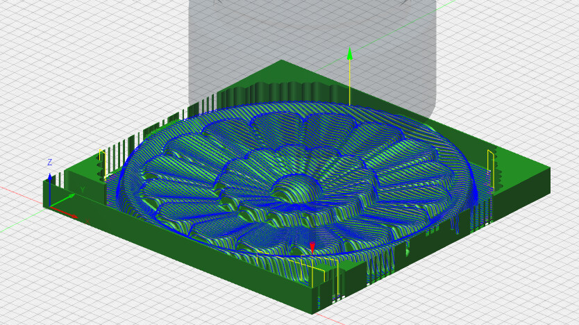
If I choose one pass , I will get this simulated toolpath:

and if I choose multiple pass , then I get this one.

I don´t understand ,because negative steps are not permitted.
any idea ?
Uhm, that looks awkward. It looks like it’s moving in the air a lot of the time.
short: for detailed help, you will probably get more feedback from the forums specifically on Fusion360 (https://forums.autodesk.com/t5/fusion-360/ct-p/1234)
The best advice I can give you is to use 2 toolpaths:
- first do adaptive clearing and check the box to leave .5mm stock (this is way more efficient for initial roughing)
- do a second step with the parallel toolpath (or another one)
But start with adaptive clearing first.
You don’t have to change bits for different paths and if you select them both when generating the toolpath, they will be combined in a single gcode file as well.
ok, thanks a lot, seems that I have to dive a little bit deeper into fusion, cause LUBAN has a strange behaviour too