Hi all,
I think that some of the several problems being reported in this and other forums are caused by the same issue: the non-uniform lineal modules working speeds. I will try to summarise in one post my experience and how I have “solved” (or better said, hacked) the problem.
First of all a bit of background: I ordered my SM 350A in July 2019 (as part of the pre-sales batch) and received it in mid September 2020. I am using Luban 3.9 with the firmware version 1.9.0 .
Since the beginning I have been experiencing the infamous “Bump” in the Y-axis (more info here: "Bump" in Y-axis). Several tests after, I proved that the two linear modules of that axis weren’t moving at the same speed. I guess that one of the lineal modules drags the other forcing it to jump a step (or something similar), which causes both the noise and the displacement of the bed in the Y-axis. Thus, when attempting to cut 3mm plywood pieces, the laser doesn’t go through the same path in each pass, making it impossible to be cut.
An example of this speed difference:


And the effect of this Bump in the Y-Axis:

The straightforward solution to this problem consist on finding a couple of lineal modules that move at the same speed and installing them in the Y-axis (and another couple in the Z-axis). This was easy for me, as I found that the X-axis one moved at the same speed as one of the modules of the Y-axis.
After changing it, the “bump” disappeared and I was able to cut large 3mm plywood pieces without problems (in more than 4 passes however, but I believe that is another issue related with the non-horizontality of the bed and with the laser becoming quickly out of focus once it moves away from the place it was calibrated. It was a problem with the focus length).
However, I observed that one of the pieces that I cut, that should be 304mm long in the Y-axis, was instead 305mm. This could not be an issue in most cases, but again is another effect of these non-uniform lineal modules working speeds.
To check this I drew two lines: one of 300mm along the Y-axis and another one of 250mm along the X-axis and measure then;
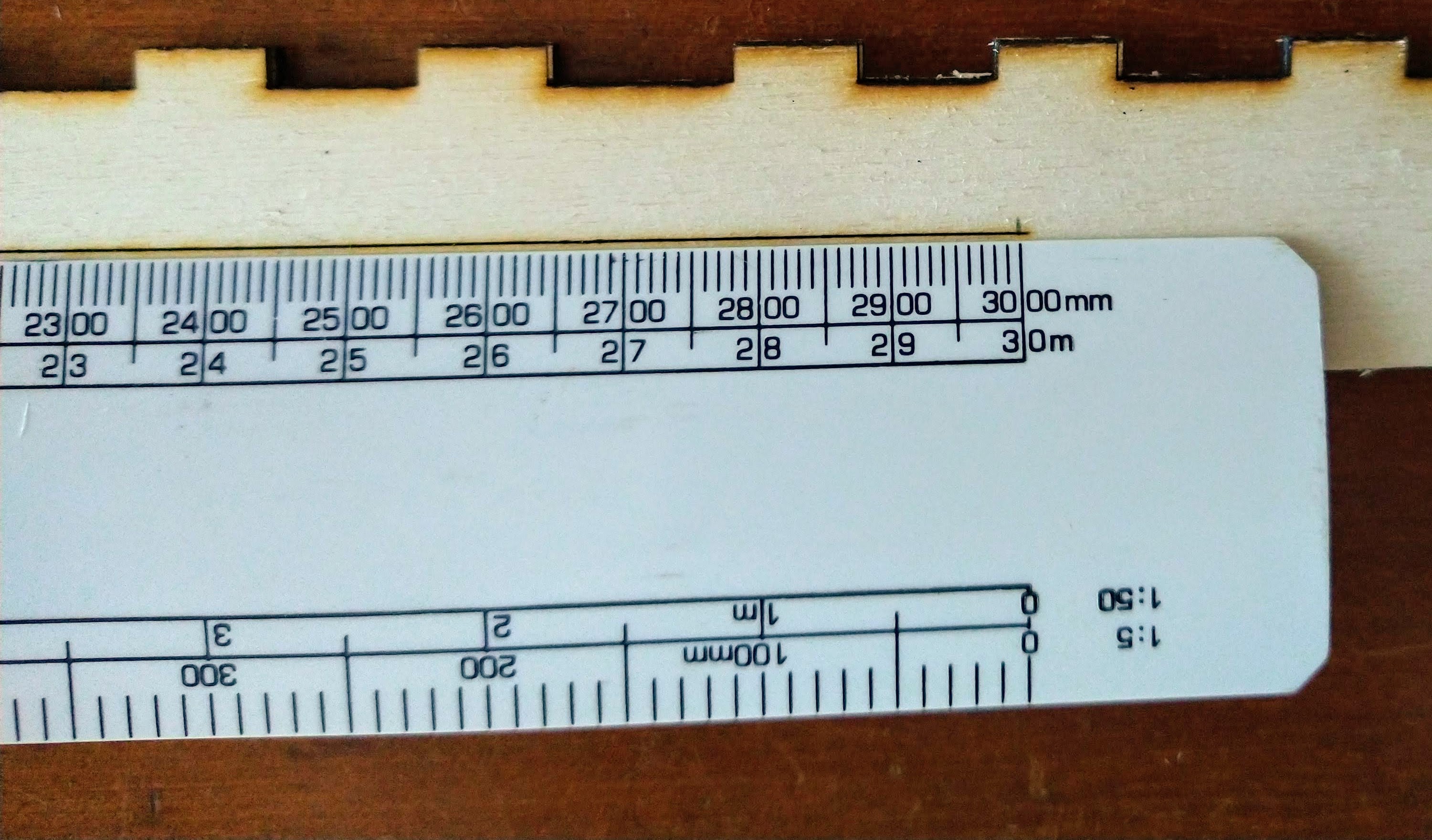

With a gauge I measured respectively a difference of +0.8mm and -0.3mm in each axis. The solution I have implemented here is to resize my drawings by a factor of: 300/300.8 in the Y-axis and 250/249.7 in the X-axis when editing them in Luban (this is, being my original drawing’s size of 290x340mm, I entered the values 290.3x339.1, so that the real cuts come out correctly sized)
It has worked, but this is more a hack than a solution.
I strongly believe that SM should change the way the lineal-modules are controlled. It looks like they have implemented an open loop (this is, knowing that the lineal modules move at a speed of Xmm/step, if it needs to be moved 1mm, 1/X steps are made) instead of a close one (in which the position of the lineal modules are corrected in case the speeds are not the theoretical one, which is the case).
Another good solution could be a way to calibrate these speeds, so that the Snapmaker could adjust their working speeds to correct these little deviations.
Finally, technical issues apart, I have to say that the initial emotion that I felt after receiving the machine has quickly blurred after experiencing and reading about the problems that people are having with the machine. I really hope that the SM team will be able to cope with them and bring solutions to their community. By the moment, I have opened a ticket with the support team.
Regards,
Xabier