I had a project where I mixed 1.6W laser, 10W laser and 40W laser, and I had a lot of setbacks and frustrations, which I decided to investigate a bit further. Here the results - spoiler: Inline power implementation for the 10 W is buggy, and trapezoid power implementation is not working or buggy.
Lightburn, 10% oversan, bi-direcional line fill, constant power
Lightburn, 10% overscan, uni-directional line fill, constant power
Lightburn, 10% oversan, bi-direcional line fill, inline power
Lightburn, 10% overscan, uni-directional line fill, inline power
Luban, 10% overscan, constant power (bi directional, cannot be changed)
Luban, 10% overscan, inline power (bi directional, cannot be changed)
Luban, 100% overscan, constant power (bi directional, cannot be changed)
Luban, 100% overscan, inline power (bi directional, cannot be changed)
Trapezoid problem is the same, but in addition, the edges, when using inline power, are not straight any more. The laser turns on and off at the wrong positions. I assume they botched the inline + trapezoid implementation…
Good: With more offset you can compensate for the burnt edges in constant power mode…
Lightburn, 10% oversan, bi-direcional line fill, constant power
Lightburn, 10% overscan, uni-directional line fill, constant power
Lightburn, 10% oversan, bi-direcional line fill, inline power
Lightburn, 10% overscan, uni-directional line fill, inline power
Luban, 100% overscan, constant power (bi directional, cannot be changed)
Luban, 100% overscan, inline power (bi directional, cannot be changed)
You can’t see it well, but with 10% overscan again burnt edges, so trapezoid still broken.
Conclusions:
10W Laser with inline power will spoil your results
When using scanning techniques (line fill, photos…) make sure to have enough overscan activated if you use constant power mode
When you use anything like “on the path” or Lightburn’s offset fill, you’re screwed: With trapezoid power not working properly, the speed changes of the laser with complicated shapes will cause inconsistent engraving depths. This is painful, as it takes away a lot of use cases!
I guess I’ll bother support with that - they need to fix these bugs.
And here’s an update: Turns out I’m wrong after all regarding Trapezoid power!
I asked in the Lightburn forum if the offset fill job setup could be modified so that at sharp corners I get overscan. This led to a bit discussion, which finally let me understand how things work - I seem to have been exeptionally obtuse here not understanding this earlier:
Constant Power Mode means laser is started with M03 - and this actively switches OFF trapezoid/s-curve power
Non-Constant power mode starts the laser with M04 - and this activates the power compensation
Inline power is just independent from that. ← It is a beast of its own, and I need to test this separately. It is neither M03 nor M04, but the G1 command include Sxxx - and if this properly uses trapezoid power I need to test - later… EDIT: See below - no trapezoid power with inline power EDITEDIT: It does! Combining M04 with Inline power does do power adaption!
Now comes the mean part which made me despair: Lightburn Snapmaker profile has a bug - regardless if I select constant power mode on or off in Lightburn job setup, it always issues M03, i.e. constant power in the GCode! And that lead me to believe trapezoid power is faulty in the Snapmaker implementation. I apologize for my wrong accusation!
Some people say (incl. Lightburn support): If you have issues with the Snapmaker profile, use GRBL profile, works just fine (it, e.g., addresses the problem with Air assist). So I tried GRBL - but this then has a problem with my much loved offset fill job setup - the laser turns off after the first move.
Long story short: I will do three things:
Try to convince Lightburn to correct the Snapmaker profile for this plus air assist
As long as the bug is there run a search’n’replace over Lightburn GCode to replace M03 with M04
Reveisit this test here, as my interpretation of the results may suffer from the Lightburn bug: Laser Inline Power processing slow?
EDIT: I guess I should also revisit PCB etching with the 2W… would suffer from the same bug… Huh, lots to do the next weeks…
What remains is the problem with the 10W. This also is visible with Luban generated GCode.
Finally, here’s a picture of my tests:
Top row - unmodified Snapmaker profile output: First: Square, offset fill, constant power OFF, next: Square, offset fill, constant power ON, next: Square line fill, constant power OFF, 5mm overscan
Middle row: Same setup, but GRBL processor
Bottom row: Same setup, Snapmaker processor, for second and third square manually replaced M03 with M04 → Success!
I got some interesting results for you. I was going to do a test of using G0 for overscan, and decided to rerun the test with M4 as well just to see what the hell. For reference; I’m using GRBL-M3 in Lightburn for this test. It seems doing a find/replace of M3 to M4 using this profile actually works fine. However, the regular GRBL (no M3) with variable M4 mode does not.
Anyway the results! I purposefully ran the power a little light so variations in power would show up better. 0.5 fill to identify each line, along with a line mode for an outside trace. This is with a 10W.
Bottom left; Regular M3, no G0 for overscan.
Bottom Right; Regular M3, G0 for overscan.
Top Left; M4 swap, no G0 overscan.
Top Right; M4 swap, G0 for overscan.
That top left with M4 looks pretty clean and even. Bottom left was pretty much as expected for M3, corners a bit darker, but otherwise good. The G0 for overscan in the bottom right was a bit of a shock… why are the edges darker. However, both M4 results look decent, and the very tips of the corners seem to fade slightly, so the power is pulling down a smidge as it should.
I’m surprised that the M3 squares look differently. I would have expected the left bottom to look the same like the bottom right, as the laser should accelerate and deccelerate at the edges in both cases.
Would you mind to share the GCode? Would love to understand this…
Thanks again Aaron for pointing me to Snapmaker’s profiles.
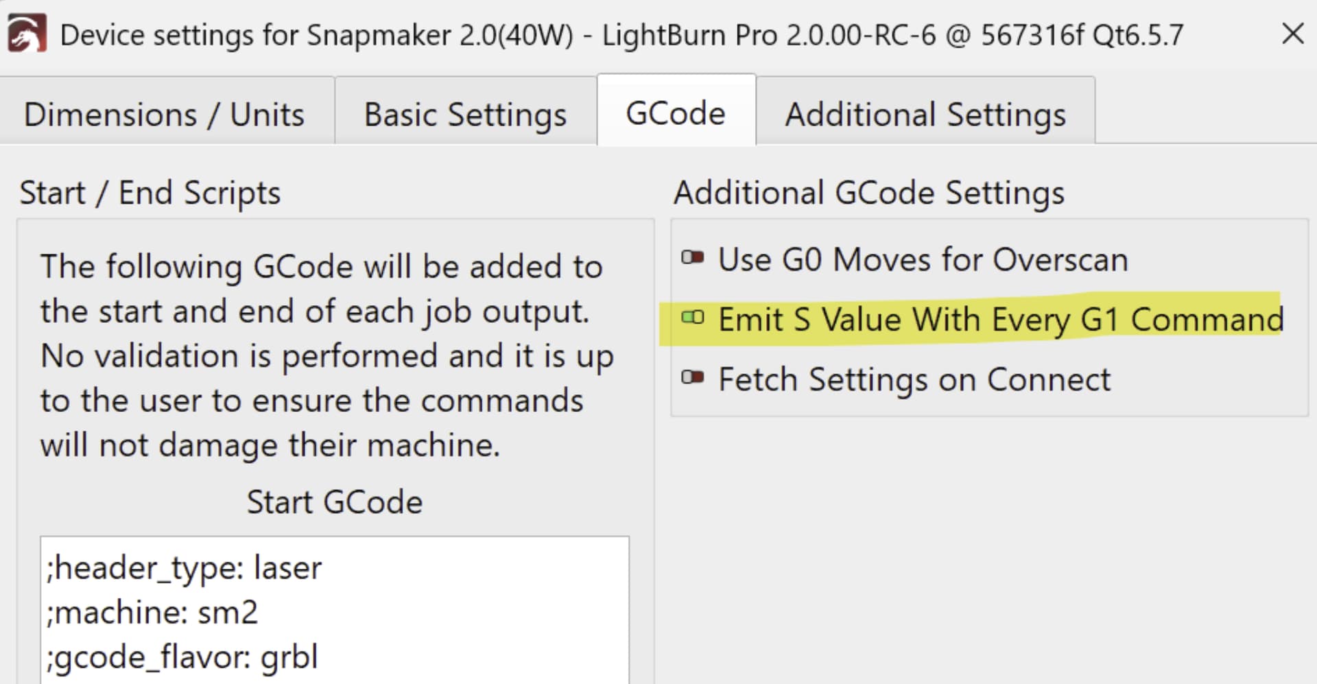
If you do not want to connect via Serial but just export GCode and transfer it, and if you use absolute coords, you may even use the 40W profile, switch off the laser offset, you can use one profile for all lasers. The GCode is basically interchangeable between all Snapmaker laser modules.
In addition to the “Emit S value…” change, the Snapmaker 2.0 profiles state a work size of 400x400 mm - that’s the Artisan size. But this is easily mended via Edit Device.
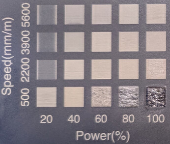
Here’s the GRBL test (same job setup as in my second post) with 1.6W, 10W (bug still there - Snapmaker ticket open), and 40W (Air Assist working):
Not perfect - but this is to be expected: the power compensation algorithm not necessarily matches the material reaction to the laser, which most likely will be something very non-linear. Thus with wood you get the white cross with offset fill. With other materials it might be better.
Oh, and last remark: The 2W IR laser profile from Snapmaker now adds Air assist (which does not make sense, as the 2W does not have Air Assist), but uses the Marlin base and has the M03 bug - M04 is not used - I discourage the use of that one…
Ah, I get the difference. In the “No G0” variant, overscan is done by G1 commands with S0 - laser power 0 - i.e. inline power. In the G0 variant you switch laser on/off via M3/M4 - M5 and then do the G0. And that’s basically the “old” behaviour: With constant power and G1/G0 moves interchanging, the laser always stops on movement change.
Still, it inspires me to test if M4 + inline power would mean inline power with trapezoid if I only use G1 moves… Huh, will test later.
Interesting results of more testing! Inline can actually do Trapezoid power! When i just create Inline GCode from LightBurn, It looks like that:
M107
M05
G0 X3.12 Y3.12 F0
G0 Z0
; Layer C00
G1 X2.88F6000 I S255
G1  Y2.88 I S255
G1 X3.12 I S255
G1  Y3.12 I S255
M05
G0 X3.24 Y3.24
G1 X2.76 I S255
G1  Y2.76 I S255
So laser is switched on by the G1. If I run it this way, it does constant power, no adaptive power. If I modify it this way:
M107
M05
G0 X3.12 Y3.12 F0
G0 Z0
; Layer C00
M04
G1 X2.88F6000 I S255
G1  Y2.88 I S255
G1 X3.12 I S255
G1  Y3.12 I S255
M05
G0 X3.24 Y3.24
M04
G1 X2.76 I S255
G1  Y2.76 I S255
it does trapezoid power adaption! Again, M4 does the trick, also with inline power. EDIT: And it is enough to state it once.
That makes me happy - it means I can use FlatCAM code for PCB laser etching - I am just running the test from this post again - will take 2 hours or so, but will report back!
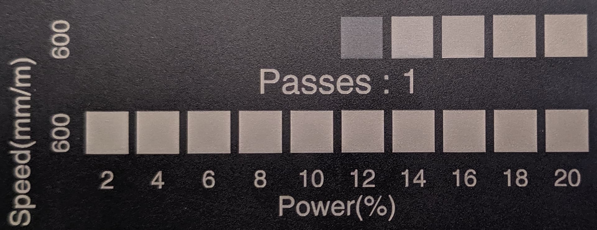
Now that I finally understood what others grasped much faster than me, i.e. that M3 is constant power, M4 is adaptive power, and that inline has no immediate connection to it, I thought I’m ready for repeating my experiments with the 2W IR laser on black acrylic and PCB etching. So I wanted to see if I could get true greyscale, repeating this experiment. Results were confusing, so I went back to systematic tests. Ran a test pattern - was rather surprised! See yourself:
Top row is constant power mode ON, bottom row has it OFF (Was running out of space, so had to squeeze the top row in)
This is test patterns done with Luban, not Lightburn. Looked into the GCode, and it is perfectly sane, the power settings should do 2,4,6,…,20% in both cases. But with constant power OFF, there’s obviously no proper power regulation.
I remembered this post by @Skreelink where he had it that trapezoid power seemed to be inverted - this I could not reproduce. Any square I created, be it with Luban or Lightburn, was behaving well.
Still, something is very odd with the adative power control of the 2W… And I was so happy that with the blue lasers it finally was all understood and working sigh
I’m back to really frustrated…
EDIT: Here’s the GCode if you want to peek into it yourself. I actually used the bottom two for the photo above.
The 2W is a completely different beast, that’s what I had done the trapezoid power test with (that you linked) and it seemed reverse. i.e. it burned when M4 adaptive was on, yet M3 didn’t scratch it. There’s definitely something wrong with trapezoidal with the 2W IR, however, it works correct with the 10W blue.
However, at the same time, even if it worked right, you wouldn’t want to reduce the power of the 2W very much. It’s already fairly low and doesn’t have much wiggle room, and might cause fading in the corners. So a good rule of thumb I’m finding is; M4 for Blue, M3 for IR.
I have been a bit in contact with Snapmaker support on my laser issues, and while I’m still in the exchange with them, there are some interesting insights I’d like to share with you, which also may explain @Skreelink’s seemingly inverted power adaption. Snapmaker support informed me:
In M4 mode, the lack of variation is likely due to the minimum power limit. For the 2W laser module, power settings below 16% are restricted, which is a characteristic of the module itself.
My current interpretation is, that the algorithm that calculates the power ramps has this lower limit of 16%. However, my 2W module performs very well down to 11%:
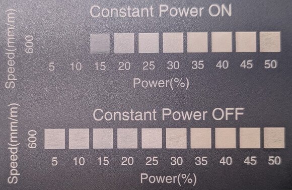
So power adjustment with speed is not accurate at the lower end - which in a test grid done with constant power OFF shows as white edges for the 20% squares - which I guess is the same as Skreelinks seemingly inverted power ramp:
This is an issue with constant power off, where the algorithm seems to introduce the lower limit. With constant power on, the laser just takes the power thrown at it, no limit:
Support got back on me for the 2W problem - with a very helpful answer! You can adjust the lower threshold that is applied for the 2W by the command
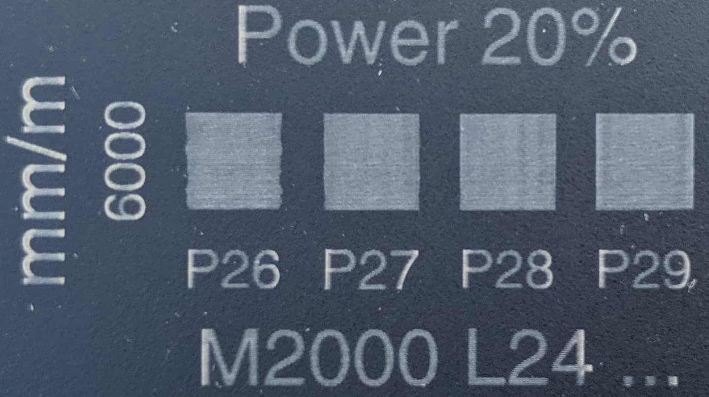
M2000 L24 Pxx
where XX is between 0-255. It defaults to P40, i.e. 15.7%.
As soon as I have time the next days I’ll try this out with the value that seems to be better for my 2W module, i.e. P26 = ~10%, perhaps I’ll compare it to P28 = ~11%.
Will keep you posted! But really glad that Snapmaker implemented it adjustable!!!
It still bothers me, and I’ll continue to complain about the fact that all custom gcode commands are not fully documented on their wiki. They can have a section dedicated to advanced/do not use unless support says, but it should still be documented for power and advance users.
Aaaand (drumroll): Success! The command works as suggested by support. So for my module M2000 L24 P28 is the sweet spot. See picture - the text was done with default M2000 L24 P40, the squares as indicated. You can see that the squares are good, and the text is not.
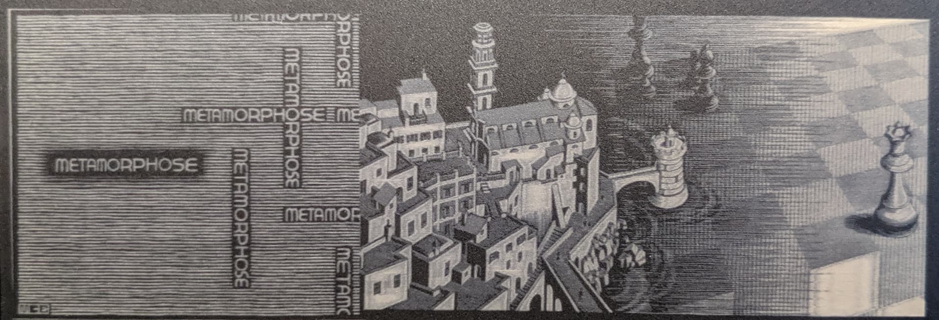
True greyscale is so much better than dithering! Here’s the same image done with dithering (you may need to go to 100% view to really appreciate the difference):
And yes, laser processing is slow. The image shown here was done with base speed 6000 mm/min, which is basically never achieved. I’ll do a run tomorrow with 600 mm/min, which I expect to yield better results - the algorithm for adaptive power struggles in places as you can see. I assume going slower will iron that out, and in effect it will make no difference as to how long the image will take to burn.
Re-tried PCB etching, now using M4 (And M2000 L24 P28). Results are again unusable - soot, nearly burnt through PCB. I admit that I do not understand why, as my test squares were plain perfect over a wide range of parameters, but real-world PCB seems to introduce too many variables. I might be motivated to investigate further, if it was not clear that even if I got it working, a medium-sized PCB would take a day or so to get etched with the weak 2W and its tiny focus. This is just too slow for my taste. So I give up on PCB - who knows, perhaps there will be a 20W IR laser some day…?
That said, with what I learned and the M2000-command from support, I feel that the 2W for anything involving intricate engravings is really a excellent device - perhaps the best of all the lasers Snapmaker so far issued. Very happy!