Hi all,
I started looking into Laser engraving with my Snapmaker 2. When I prepare an image in grayscale mode, I see that Luban dithers the image, i.e. “simulates” grayscale tones by kindof random black and white pixel patterns. I was wondering: The laser energy can be fine tuned between 0 and 100% - would that not bring the possibility to do “true” grayscales by darkening the target material in different degrees? Is this a stupid approach? Can the material only get black and white?
Thanks for any insights!
Hauke
I have threads that may help… Grayscale is only dithered… no true half tones
and so the laser does what it does regardless.
Here is discussed the dithering and grayscale images.
Here is the way the laser and wood work and it may help
Hi @jepho,
thanks for pointing me at these posts: I fully understand the concept of halftones and dithering - back in the days when you could not afford a colour printer I played quite a lot with that to get decent prints from a black and white printer. What I fail to understand from the posts is if or if not its possible to scorch e.g. wood in true gray tones, i.e. if I need 100% laser power for x seconds to make it pitch black, would the wood get only grayed if I apply 50% laser power for the same time? Or is the laser not working that way, is the transition between unscorched and black that steep that you basically can only do black and white like b/w printers do, which would force you to fall back on halftones & dithering?
Cheers
Hauke
An afterthought: From the posts you linked one thing caught my eye: And thats someone from staff pointing out that line mode is kindof true greyscale. So I looked at the G-Code for line and dot mode. Dot mode is a long sequence of Go to a coordinate, switch on laser full power, dwell for a few milliseconds (always the same value), switch off laser and move to next position, actually doing classical dot dither. Line mode is switch on laser full power, move to some position, and switch off laser, move again. The movements with laser on are at the same feedrate, but different distances. So it does not draw dots in patterns, but lines in different lengths (which you explained well in one of your posts). So both are ways of dithering, not “true” grayscale.
I think I need to play around a bit myself and write some G-Code manually working with the 255 power levels Marlin firmware allows the laser to be set to. And also working with different feedrates wile having the laser at full power.
Hello @Hauke; Part of my technical discussion with the staff member was to underline the issue that there was no response from the laser to tonal value because the values of tone were randomly generated according to the dithering algorithm. The dithering algorithms appeared to make the laser apply whatever value was implied in the image via the algorithm for the laser power and dwell time in order to produce some sort of image.
My experience for the dithering was that the image was so poor that there was no intelligence being applied. I expanded a section of an image to show that beam frequency was being modulated needlessly for areas of flat tone (that dithering algorithm again) while beam amplitude was not adjusted. The staff member finally agreed that dithering was the process being used not half-toning as was initially being maintained by that staff member.
My halftone demonstration image was to demonstrate that switching a laser beam on and off without dithering could work well if the principles behind halftone image were applied. In other words instead of getting the beam to mimic a subject image by calculation of dithering to imitate tonal value, use a specific power of the beam as in my example halftone image to apply the same tonal value (colour) at different strengths of laser beam.
No further discussion on this issue has taken place with the staff so I presume they are happy with the present unacceptable attempts to reproduce images by means of laser beam. I have had good results from single tone images (my attached tree images on plywood) suggest that heavy and light laser beam application would produce more tonally realistic images than dithering. I feel that accepting that tonal limitation and working to reproduce the old reprographic halftone methods would be a far easier step than trying to make the laser beam imitate all tonal values in an image.

I did not go as far as to look at how one might adjust the g code because I was very new to the world of 3D printing/laser and CNC and had insufficient knowledge to adjust things. Reprographically, I have experience but not applicable to laser work.
Hi @jepho,
OK, thanks for pointing this out - I somehow did not read it properly and thought you explained to the forum why dithering is OK  My stupidity. So we’re both on the same side here I will keep you posted what I can work out from the GCode. What strikes me is that Laser-control on the touch screen allows even sub-% adjustments, while the standard Marlin G-Code only offers 256 intensity steps, which I guess is historically motivated since the ATMega controllers Marlin was created for initially had 8-bit-PWM control.
Ideally of course it would be possible to run the laser at full power as much as possible and use movement speed to adjust energy deposit, but this may be complicated due to accel/deceleration of the machanics…
Whatever I find out, I’ll let the Forum know
Cheers
Hauke
Hi @Hauke; That is a good idea. My feeling is that just 10 values at 10% difference would reproduce sufficient tonal difference for monochrome images… as per halftone screening. Not much tonal variation is required for the eye to detect a difference and the brain fills in the details it thinks are present… at the correct viewing distance of course.
I don’t think the image below needs much in variation to produce the tonal difference illusion.

The following images are from a single flat tone (pupil) and they show the laser beam is being frequency modulated but not adjusted for amplitude.


The base image was this and the enlarged sections of the dithered images above were taken from the pupil of the left eye (as we view it) of the male.

OK folks,
started to dig deeper. I wrote some G-Code that creates a 5x5 cm square, divided in 100 5x5 mm squares, each having 1% more in laser intensity: GraySquare.nc (70.5 KB)
I printed it with feedrate 10000 mm/min and 20000 mm/min on plain light gray cardboard. The results are… interesting, but, sorry to say, rather disappointing:
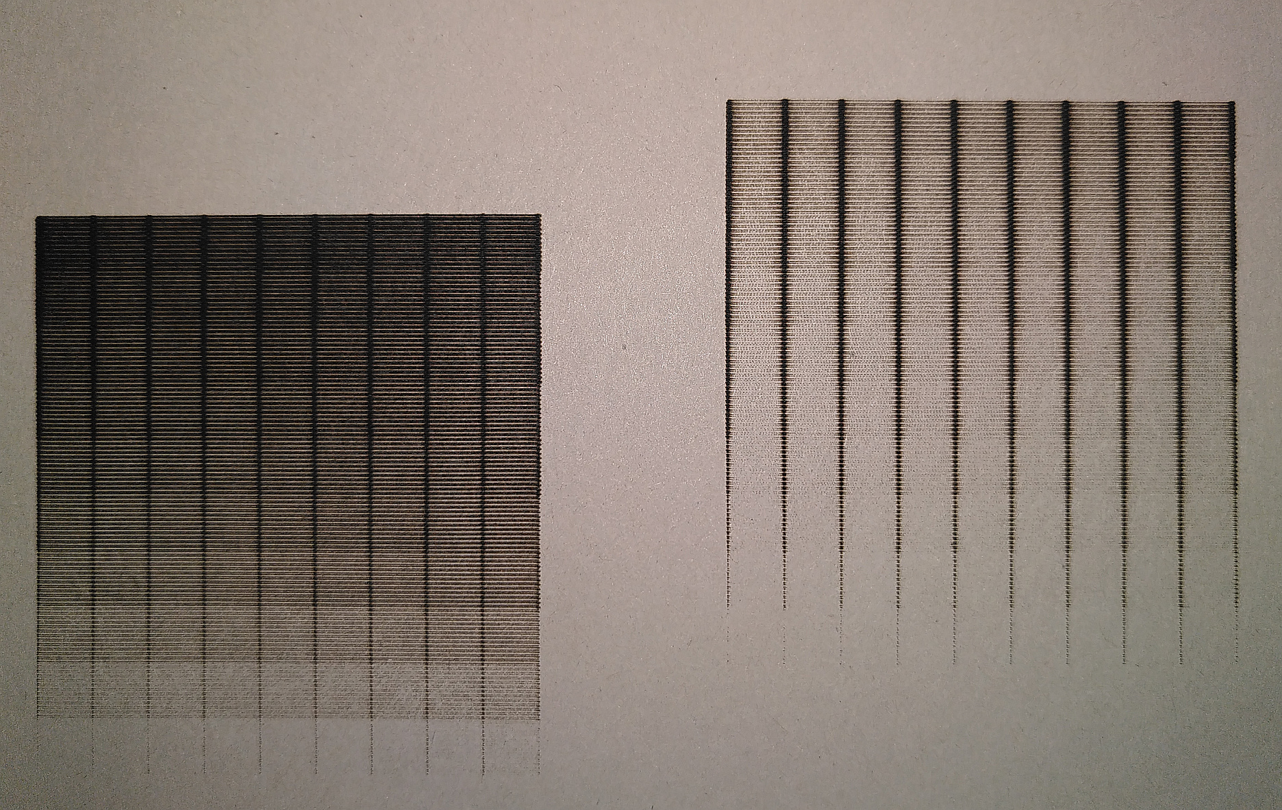
While I in general was able to produce gray tones, they look dithered.
Two possible reasons:
- PWM is so slow/lo frequency, that the head movement resolves the individual pulses. That would actually be shockingly slow PWM!
- They do not do PWM, but calculate a on/off pattern for the given intensity and feed it to the laser in software, in other words, they do software PWM - that would also be shocking - any modern MCU can do hardware PWM - why do software PWM?
Also, you can see the effects of decelleration and acceleration - the head slows down after each movement command. This is what produces the dark lines, they are not part of the GCode. I guess this is something you could work out.
I don’t think that’s the road to success, but I have another idea up my sleeve, will try this the next days…
As of now: @staff, please tell: Are you doing software PWM? would it be possible to switch to high frequency hardware PWM? Or is the laser control pin/power transistor not capable of that?
I sicerely hope they can do hardware PWM…
A bit unhappy right now…
Ah, and another observation, not strictly connected: In Luban, the code is displayed correctly. However, if I run boundary via touchscreen, it fails. This is obviously because I use relative movements, not abolute. @staff: Would be great if “run boundary” could also interpret relative movements. Not doing so, may cause unhappy surprises…
@Hauke: Nice work! I agree that the finished result looks dithered. After accurately specifying the energy level and area in G-Ccode, the set value of energy is contaminated by one or more of the processes used for depositing the energy specified. I look forward to the results of your next test series. Thanks, I appreciate you taking out the time to work with this issue.
Thanks for taking time to test that out, @Hauke
I hope this info helps, it may just be repeating what others have mentioned in a different way.
I would think if the power PWM is constant but velocity and acceleration vary, there is no way to get a consistent gray scale line.
If you made velocity constant (with zero acceleration), a single PWM should give a more or less uniform output. However turning and changing direction would suffer (unless you went slow, maybe took the power down too).
Alternatively, there would need to a map of velocity to PWM in order to produce a more or less uniform line.
A final option that comes to mind (granted it would take much longer) would be to laze several passes, each one adding another layer of darkness. Each pass would add more contrast, and would always tend toward less information.
I’m sure there are other solutions out there, once I receive my A350, I’ll be sure to tinker around with this more!
All the best,
ODINTE
I am rather sure that with a bit of G-Code tweaking I could get velocities constant enough to not have the adverse effects of acceleration and decceleration. Did not bother yesterday to solve this, because it became clear to me that with the current PWM I would not gain anything. Multiple passes might improve, but only for materials that blacken slowly. If they go dark fast, even one pass might be a problem in darker regions.
What I will try the next days is to play with a combination of laser power, dwell time (like in the dot mode of Luban), and perhaps even slight defocusing of the laser. I guess that might work, but it will be much slower than the mode above. The 5x5 cm square was done in ~5 mins, I expect the “dot” method to take hours to draw the same square… Which is a pity, because with fast PWM I’m 99% positive that my method above would just work, and imagine what this would mean for the speed to laser down an image!
Finally some tweaking needs to be done since the blackening is most likely a process following an exponential curve, but when I reached that point, I’d already be very happy…
Just did a bit quick’n’dirty research - as expected STM32 microcontrollers (which I understand is what Snapmaker uses) are well enough capable of hardware PWM at higher kHz frequencies. Doing the math:
Suppose movement speed is 100 mm/s, then:
PWM = 100 Hz --> 1 pulse per mm --> unbearable bad
PWM = 1 kHz --> 10 pulses per mm --> assume 10 pixels per mm --> 1 pulse per pixel --> 255 grey tones possible with 8 bit pulse width, assuming that the material reacts perfectly (which it would not)
So I’d say 10 kHz PWM would give the necessary flexibility to account for material variations, perhaps higher resolutions etc. And of course: The more the better! And most MCUs are absolutely capable for high frequency PWM.
I was also thinking about laser power modulation instead of dithering. The problem I see is that materials differ and the response is very unlikely to be linear with power. But, there’s a camera on the laser module. New calibration, print a greyscale, analyze with the camera, compute the necessary power curve, similar to gamma correction on monitors. Save the correction on a per-material basis. Trivial? No. But hey, it’s just software, right?
Hello @Hauke; I have been considering what you said regarding constant velocities. Could you program the code to switch off where it does in your pattern currently but keep the laser moving past that edge for a distance? Then when the laser stops and reverses direction, keep the laser off until the point you want the laser beam to turn on again. It would make the engraving slower but you would have negated the variable velocity effect and only use the laser beam at the point where it has gained its programmed speed and is always moving at the specified speed when turned on.
One other thing that occured to me when I considered my halftone image is this; it is effectively a 1 bit image which only requires off or on to replicate it. Can this be coded so that my halftone image (psuedo continuous tone) could be engraved? I guess that the idea of moving the laser beam (turned off) past the workpiece while it moves one scan line and reverses direction and then accelerates to the point it is turned on again, would work well for this method too. I feel that halftone will be more accurate than error diffusion dithering.
The only proviso would be that the centimetre or so of space to run the laser past the workpiece would mean moving the workpiece further away from the edge of the bed. My 130mm square bed would permit say… no more than 100mm square to be engraved.
edit to add a monochrome .jpeg image with a round halftone dot and a screen angle of 45°
You can download it and use it for your tests if you want. It will enlarge twice when viewed on the forum viewer so that you can examine its structure. Magnified once it appears to be continuous tone from around 2 metres distant.

I think this is possible. But would Luban B/W image not do exactly this? Just asking, never tested…
I have had mixed results with Luban displaying all manner of artifacts. It inverts colours in Vector, even when invert checkbox is selected. Appears to place artifacts on display and does not respect halftone dots but changes their shape. I will try this out and send you screen shots.
What are people using for laser gcode generation? Luban certainly has a ways to go, and for CNC it’s awful. I’ve done 2 laser runs so far, the box sample, which worked great, and a photo on cardboard. Photo took forever in greyscale (almost 3 hrs) even though the print was only 3" x 4". Burned thru the cardboard top layer on extended black areas, not a luban problem, just my inexperience (I think). Need to reduce power. Slightly off-topic, but is there slicer out there that does 3D, laser, and CNC well? Or, do I need different apps for each? My primary use is going to be 3D and laser. Thinking about Simplify for 3D printing, but it actually cost money.
Hopefully I will receive my SnapMaker 2.0 and will be able to test some of this myself in the near future.
I had a question about the gcode you provided. When setting power, I notice you are setting both the P and S values (a percentage 0-100, and an 8-bit 0-255).
M3 P31 S79
Are both needed? Or is one sufficient?
e.g:
M3 S127 ; ~50% power (8-bit scale)
M3 P31 ; 31% power
I pulled the g-code reference from this post:
Thanks!
ODINITE
I just took Luban created GCode to “spy” at, and in there they set P and S both, which made me wonder. But I did not bother to try only S or P yet.
The complete list of G-Codes is indeed nowhere, but they basically use Marlin, so any Marlin reference is a good starting point. Like this one: https://marlinfw.org/meta/gcode/