After almost finishing the final touches on the assembly of my A350 enclosure I noticed that the wires from the controller were interacting with the right side door. I didn’t particularly like this arrangement.
I have now moved the controller to the left Z-axis. The following changes were made - none of them permanent.
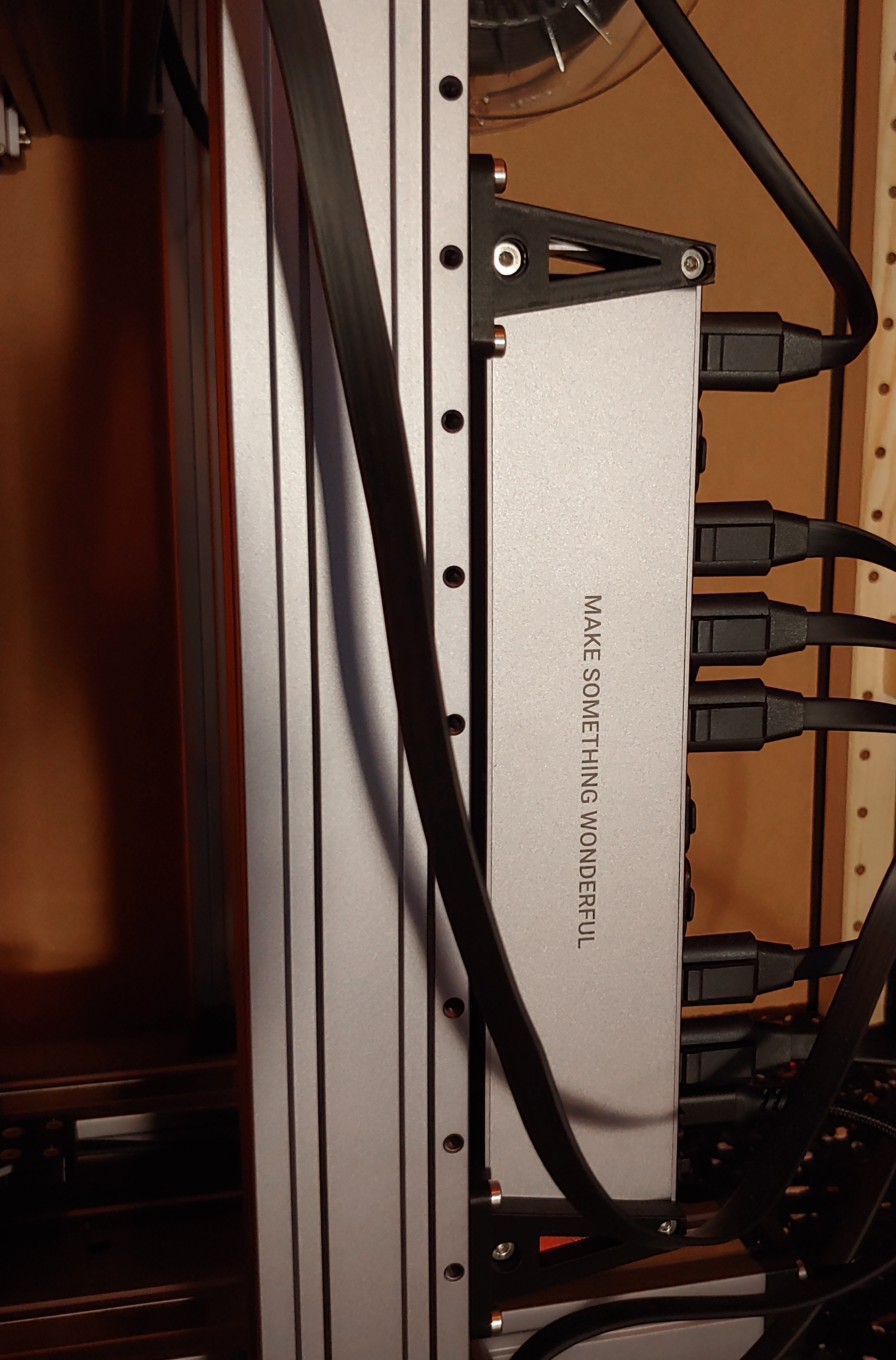
- Move the controller to the left Z-axis.
- Move the tool head cable clip to the left Z-axis.
- Flip the X-axis over.
- Flip the back panel of the enclosure.
- Move the exhaust fan to the other side of the back panel (including cable clips).
There are some impacts.
- The tool head home position is now near the door.
- The X-axis is inverted.
- The module no longer covers the entire build plate.
- Accessing the controller is not simple.
- The exhaust fan changes sides, as does the location for the power supply.
I realise that accessing the controller is now pretty hard, but I figure that this doesn’t happen all that often. It might be that I add a connector to the heat bed wire, so I can leave everything plugged into the controller. I will likely add a USB extension lead to the USB socket, so I can insert a USB stick from outside the enclosure. I will also add a USB-C extension lead so the remote control can sit more comfortably with the coiled wire not being so tight.
The X-axis inversion means that you either need to flip each design - not an issue if it’s symmetric around X - or you need to update the firmware. There is a feature request to implement this as a tick-box - Feature request: Snapmaker Linear Module Inversion · Issue #63 · Snapmaker/Snapmaker2-Controller · GitHub.
The inversion also results in a different placement of the tool head in relation to the build plate. This is a combination of two things, the software prevents the X-axis to be used entirely, but even if it was able to be used, your tool will still only just reach the edge of the bolted bed.
I’m not sure that you need to adjust the home location since the homing near the door seems like a great side-effect.
Disclaimer: I’ve only just put everything together. I’m still waiting for my dust collection to arrive and I need a few more bits and pieced before I make any chips/fumes.
Given that the user manual for the enclosure covers both A350 and A250, I suspect that this method will work on the A250 enclosure without any issues. I don’t know how the A150 or the Original SnapMaker enclosures are constructed, nor do I know if this change makes any sense in those devices.