Idea for quick switch bed: feedback requested

I kept thinking about your reply. The laser has these cutouts where the screws go. What if we glue in some magnets there. The base board can incorporate cutouts for some metal pieces that can be glued in place and then that might be enough to keep those in place.

To increase friction some cutouts for a rubber strip could also be foreseen. That might then also be sufficient for the printbed. This does mean incorporating more and more materials and keeping it all perfectly flat becomes more of a challenge again.

It would make mounting the printbed and laser plates completely toolless though… Just snap it on there.

I still wouldn’t trust it for the cnc. (depends on what type of work you’re doing on the cnc)

Always too much ideas…

1 Like

I guess for the CNC you just remove all the stuff above the base plate/waste board.

Not to completely derail all the progress that’s been made on this so far, just offering up a shower thought I just had:

What if instead of magnets as a retaining mechanism it was a cam lock and slots, here would be on the right of the diagram which I imagine would be the front of the machine:
image

Something like a bed frame quick release:
image

Or even a sliding locking mechanism:

There’s got to be a simple, elegant way of inserting the rear of the work table into a locking mechanism, then latching the front so it’s secure for even CNC.

I’ve been thinking along slightly different lines for a while. Not only for bed-holding, but also tool and work-holding.

The idea is that you use existing threads in build-plates, tools, etc. and use the stud or dowel to repeatedly place the item in the exact location.

Clamping becomes a separate issue using the above “alignment”.

o

Another off the rail idea… I don’t know if you’ve ever seen these snap together “hook and loop” substitutes before, but they are in credibly strong.

The adhesive would give before the snappers would, so maybe making some kind of frame / brackets out of sheet metal that binds it to the bottom plate, then a recessed 2nd plate which has the table you wish to use to clear the frame.

I love this stuff.

The rolls of this appear to come in up to 3" from mcmaster, perhaps you can get wider rolls from a different distributor who might specialize in this sort of thing. I am pretty sure these are made in wider rolls then cut to size. most things like this are anyhow.

i think i might fiddle around with this a bit.

That could be an option, but then it would be better to also add the inserts in the base plate so you can use those to clamp your workpiece.

As I want the base-plate to be my flat reference. and just want to mount it once and never touch it again, my intention was to put a wasteboard above for which it isn’t a problem that it gets damaged. And potentially in a slightly softer version of MDF.

That’s why I wanted to create a topic to collect different ideas before spending hours making stuff and see someone else come up with a much more elegant solution :wink:

I do like the idea of the slots and actually it was on my mind too. Not in the tilted way you described (which is quite fool-proof) but with tradtional t-slots. And then a lever on the side to lock it. 2 slots front to back and 2 levers on the front and on the back would be enough I think.

Or a catching latch (not sure about the terminology here :sweat_smile: ). Basically like a dowel pin sticking out of the base, from the side a “hook” type latch that catches it and as you close it also tightens it.
Something along the lines of this (but also pulling it closed, not just latching):
image

Another variant is like a “chest-lock” or the type of spring locks you have on a spring-form used for backing. like this:

But with both of those options I was struggling as where to attach those. For the box lock I was thinking underneath the base plate and have them pull down on the front and back, but you don’t have that much space at the bottom to put these.

Yes! That’s where the inspiration for the cross-shaped cut-outs came from!
Why not just use round dowels? The projects I’ve done with two sided milling have learned me that if you just put them in wood, the holes will start to show some wear and they will get loose, so i wanted to use the cross shaped section to make it less susceptible to this. (because there is friction in all directions. Another solution would be to make the holes a bit bigger and insert a piece of tube to avoid that wear.

Your idea is also along the lines of what @brent113 mentioned in this post: New quick toolhead change print - #15 by brent113

That was my first idea in combination with the box-locks, but I failed at finding a good place to attach those.

So should I consider this to be like a sort of velcro on steroids? Or does it also help to align the two connecting pieces?

Finally some updates from my side:
I have been tweaking the model a bit more and cleaning up the openscad code a bit. I intend to have it online on github soon. Mostly to make sure I do proper version tracking for myself as well :wink:


It came out pretty well (on the right hand side you can see that the toolhead doesn’t reach far enough to make the cutout of the handle. Left and back work out just fine. The front just falls short but you can easily break out the remaining piece.

The good news is that all holes align up perfectly (yay!). I did do a quick test by running a calibration with the 3d print heat and just the sheet on top of the wood and it looks pretty good. There is still a deviationm but the surface is flat, just tilted. (hence the idea of machining it flat. Or this board could just be shimmed.

I modified the through holes for the carriage bolt so I can fix those to the build plates with a washer and nut from the bottom as well. (in stead of just having the hole there. Should make installing easier.

And as they say: measure once, cut twice (or how exactly did that go? :innocent: )


The location of those through holes is actually ok. It’s about 7mm away from the carriage. Which is ok for a normal bolt, ok for the type of clamps I first intended to use there but not for the wing nut I wanted to use for initial testing.

Nevertheless, good enough for a first iteration and doing some more testing with it.

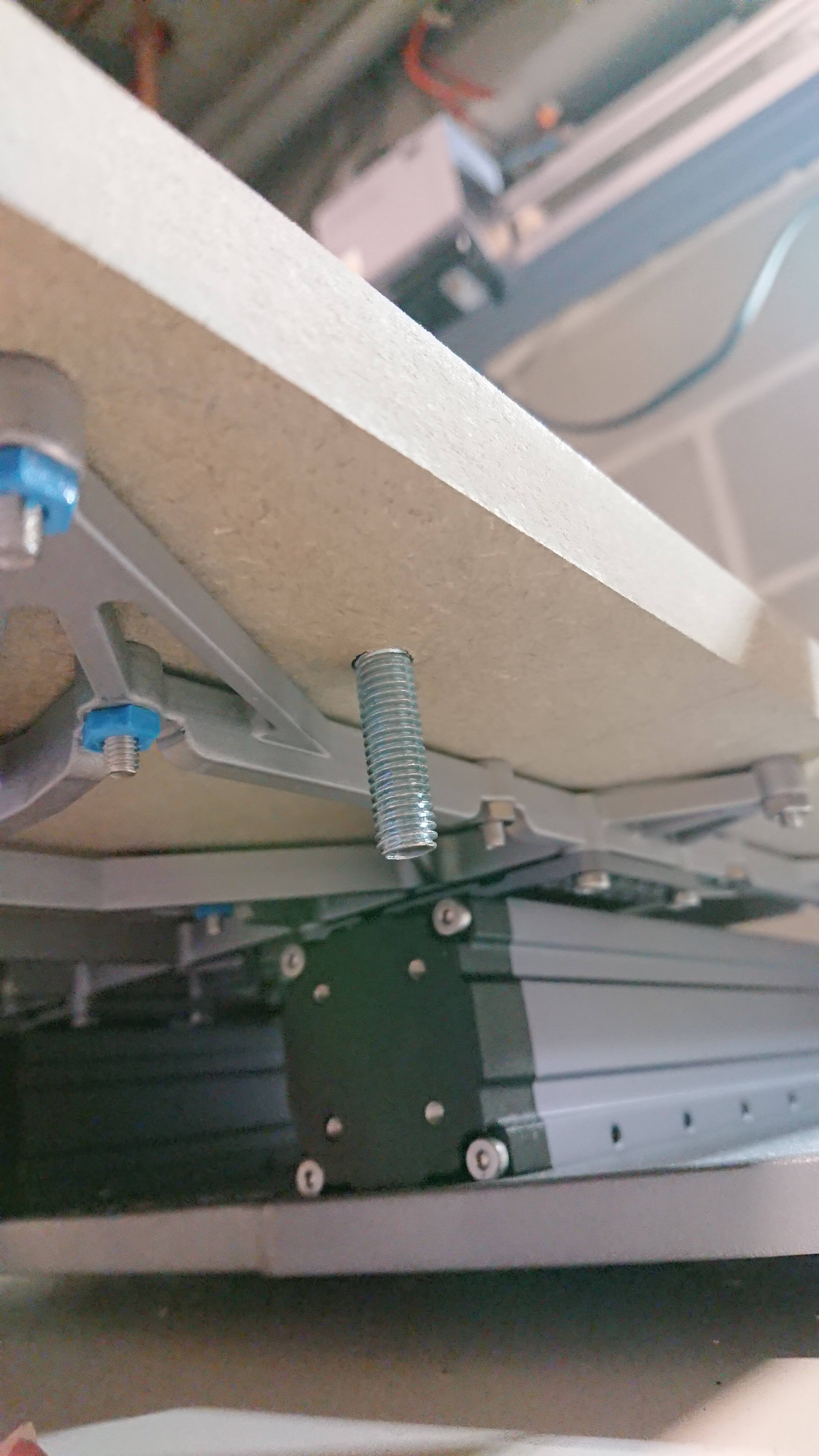
But because magnets are fun, and it would cooler if I didn’t need screws/clamps at all, I finally did order these (pot magnets):
image
25mm diameter and supposedly 18kg of pulling force.

I chose those with the threaded barrel so they can easily be adjusted in height if needed. (and to prevent having them glued in place and just ripping them out every time because the magnet is stronger than the glue.

combined with these:


because they have a small border, that will prevent them from sliding away.

I figure that 3 or 4 of those magnets in the base plate should be enough to keep it in place.
Or maybe even already impossible to remove without a crowbar :sweat_smile:

I’ll be trying out some more stuff later this week, so if you think I should try something else as well, do let me know!

2 Likes

I think this is essentially what I’m thinking of - a thin flush mount bracket:

A pair of those on each of the corners, maybe one in the middle too for 5 pairs, carefully located so they are a snug fit (maybe counter rotated 2 degrees), would hold well in all directions except 1 (the direction you insert from). You could drawbore a pin/bolt to keep the table in tension against the hardware.

Edit:
Yes I was thinking these would be countersunk so the pieces are in contact. The one in the middle I guess would resist bending of the wood for seasonal movement if it tried to lift up. Nothing is really holding it down.

And yea, your latch previously, or any other number of solutions would work in lieu of the pin. I think it’s important to be kept in tension or compression, a simple bolt from top to bottom I don’t think would be adequate. It needs to have spring pressure to preload the hardware.

I guess if the way they are flush mounted is done just right, maybe mounted at a downward angle so the brackets are really snug and get tighter as they are inserted, then a light tap would “seat” them in tension against the friction of the 2 surfaces in contact. Then a simple bolt would secure to make sure it doesn’t loosen.

1 Like

This does look very simple and nice indeed.

It might be good to countersink them so the two plates are directly flat against eachother. To avoid the empty space between them and eliminate any wobble. In that case I don’t think you would need the one in the middle.

Alternatively to the pin the the bottom, plate could also be a bit longer or have a small extrusion in the front big enough for a hole something like a cam-lock type of latch to keep it in place.

The elegance is in the simplicity definitely. I like your idea very much.

I have used those brackets before and there is a bit of slop in them - to get them to work in this zero backlash way I think is possible, but will require careful design and CNC so that inserting them puts them in increasing tension and pulls the work table snugly onto the base. I put some additional notes above.

I think you’re definitely capable of doing that and I think the tolerances would be looser than what you’ve already done with the X inserts.

There may be a clever way of countersinking them just slightly too deep and using the attachment screws (and maybe shims) to control the tension. Getting adjustability into this, without introducing something that will loosen over time, will be interesting.

If this is expected to last a long time and maintain adjustability I’d be concerned about the wood screws provided in MDF - it will chowder out the screw hole eventually. If this was my build I’d use threaded inserts from the back (T nuts probably) with thread locker and a machine thread - at least on the base since it is “permanent” and will see more wear than each tool plate.

Dialing in the adjustment, in my head, would look like roughing in the height with shims under the brackets and repeatedly test fitting the work board, adjusting the base screws and shims until it’s perfect. Then, since the shims under the brackets control the height, apply threadlocker and tighten the screws down.

The slop sounds like something a hammer could fix :wink: but doing the mounting carefully could probably eliminate most of the issues.

It could also be an option to place them in a circular orientation, so that you turn them in place. Similar to what some light fixtures use. As you turn, it pushes both sides closer together That might help as well to get the tolerances in the fit to be less of an issue. Last weekend I struggled a lot to get it loose from one of my wireless access points :wink:

It’s a snap fit, so it’s a bit loose at the end, but the “snap” part isn’t necessarily needed here. Although I’m not sure if it would add that much value and I’m just overengineering again.

Exactly. That’s also the reason why I’m using the carriage bolts in the initial idea; to keep them locked better (and obviously avoid them to turn around as they are tightened from below.

Now my main challenge is to find the correct name in Dutch for these things to find a local store/supplier where I can get these things :face_with_monocle:

The dowel/pin part aren’t the perfect solution as you would need access from above (and the having everything premounted is kind of moot). But maybe the box lock type of latch could be used somehow.

Edit:
An extra advantage is that you can just hang the plates you’re not using on the wall so they are out of the way! :partying_face:

1 Like

These might be an alternative for the rockwell brackets as well. As they connect there seems to be a slope so that they are actually pulled together. They are significantly thicker though:
https://www.amazon.nl/gp/product/B07R4N2STK/

But they do look sturdy and like they would last.

1 Like

I quickly created a small 3d model of these to test the concept before I put in an order. (not an exact replica, but similar design) That should give a good idea if it could work. A3d printed model might even be good enough if if it is countersunk in the plate and all snug in there. (model created with a tolerance of 0.1mm for) Not yet tested/printed. That will be for another day.
preview:
slide-connectors-hook.stl (409.1 KB) slide-connectors-sink.stl (305.9 KB)
(to be printed standing up for optimal strength)

I’ve noticed that there’s no discussion on using T-slots on an extruded aluminium bed like many CNC machines seem to have.

Here’s an example:

https://makezine.com/projects/add-t-slot-bed-to-x-carve/

Is there any reason that this doesn’t seem to be considered?

Yes, it is velcro on steroids, but its quite rigid and when taking a moment to make sure all the surface is pressed together it should end up where you expect it to.

I have used this to affix removable signage on gates for some high tech self-serve convenience stores as part of a pilot program, which was a satisfactory solution for the client (who is rather enormous) due to its strength.

1 Like

Mostly because I don’t like the letter T :wink:

No, serious: T-slots are great for clamping things down. Very easy to use, They give you a lot of flexibility and it’s just a really quick when using them.

However:

  • My (personal) main goal for this project is to replace the beds as easy as possible. My initial assumption is that I have a ready to use assembly (heated printbed, laser plates etc) I can just “throw” on there and be on with it in under 60 seconds. As a consequence you don’t have access from the top. T-slots clamp things down and you need access from the top. (which isn’t the case with minimal size prepared assemblies for the print/laser platforms)
  • Could you use T-slots: most definitely yes. Just make everything a few cm longer in the Y-axis so you have room for clamping things down. This does increase the room needed at the front and back of the machine as the bed will stick out further. Also not sure if it would have an effect on stability as the bed gets longer. (don’t know how big that effect would be, might be negligible)
  • There are multiple ways of creating a t-slot plate: I don’t see myself cutting out t-slots in a board with the snapmaker :wink: (Build A MDF T-Slot Spoilboard For Your CNC Machine - YouTube).
  • On the other hand. Should we need to? If it’s to use as a base installation plate, you could just mount the t-slot profiles directly on the carriage. But then you lose the “easyness” of leveling the build plate. Then again, you could just mount them on top of a flat plate or countersink them. You would only need two profiles if the rest of the concept remains the same.
  • the other way is what you linked with a fully prepared plate. Could be very useable, but again a question on how flat those are when mounted on a the SM carriage (and what is the cost of those?)
  • A naive attempt to make the experience as “toolless” as possible. You still need clamps. (Just like in my initial idea (hence considering the magnets, which are still an option)

But probably the most important reason:

  • I do enjoy tinkering with this kind of stuff and coming up with an alternative solution is quite enjoyable as well. It’s a good way of getting to know all the functions of the machine and it would give me great pleasure if the new solution can be created just using the tools of the printer itself :slight_smile: So in stead of buying a t-slot board, have something crafted myself, just using the snapmaker. (excluding nuts, bolts and magnets obviously :wink: )

Well, one thing we definitely have learned is that SM’s choice to go with a lot of screws wasn’t just out of cheapness or lazy design.

I would think 2 or 3 t-slots with matching rails attached to the beds would work. Then have a set of pins that raise up with a sliding mechanism to lock it in place.

-S

I was thinking of using https://www.thingiverse.com/thing:4700986 to build a quick replacement bed as well.

A few tweaks and that design should work fine. I’d lose about 1 cm of build height which isn’t ideal, but should be fine.

I was going to screw it straight into the wasteboard, build a new spider for the laser base, and use the metal one for the heated bed.

I might go and tweak that design further to make it lower profile.

Do you think that would be rigid enough for mounting the bed? What material would you be making it out of?

I’m not really sure if I understand how you would implement it though.

Ok, after some fooling around this weekend I think I have a solution that will be satisfactory for me.

I’ve published all my files and OpenSCAD source code on github:

I’ve ended up going with the magnet based solution and it seems to work really well. Using 4 pot magnets the beds attach with enough force so that I can lift the machine up by picking it up by the bedplate. I assume that should be strong enough :slight_smile:

To prevent it from sliding sideways, I’ve embedded the magnet and metal counter discs into a “pot” and “lid” which snap together perfectly and consistently in the same space as well.

So far I’m really pleased with this solution. My proof of concept version works great. Now I just have to wait for my order of inserts to arrive so I can create the final versions of the top-boards.

A video of it in action (preview should work now):
https://1drv.ms/v/s!ArWNERowM_MXrVhKSm1dD6fUEsuZ?e=Vewce6
(yes it’s the experimental version and a leftover piece of wood used. Final version will be a full plate obviously :))

Some pictures, also included on the github page:

biggest disadvantage: losing up to 36mm of height. This can be rather easily reduced to max 26mm by using 10mm MDF in stead of 18mm MDF for the top plates. It could probably be reduced even more by countersinking the carriage in the bottom plate. (mounting directly on the Y-axes isn’t a viable option I think)
But for me personally, it’s a sacrifice I’m willing to make. And if needed, it’s still removable. Up till now I didn’t encounter any project yet where I needed to go that high. (Not yet at least, I’m sure this will come back to me as a boomerang really fast :wink: )

2 Likes

I think it’d be rigid enough for the bed, especially given the slop that exists currently with the linear modules (something that I want to fix at a later point).

It’s what i use for the print head, and the linear rail flexes before the printed part does.

I’m going to start off printing it in PLA and see how that goes. My biggest worry is whether it’ll handle the temperature of the print bed without warping.

If that’s not rigid / does not handle the temperature, I’m thinking of using ePAHT-CF(Nylon Carbon Fiber) | eSUN 3D Printing Materials. That material is incredibly rigid and has heat resistance well above what the bed can put out.