Perhaps a phasing error between variation in the X and Y leadscrews is causing a precession?
Is there absolutely any play in X or Y modules when moving?
I’d probably recommend rigging up a measurement device like a dial indicator and doing circles and also just X and Y movement isolated - I’d expect to see a slight change in Z in one but not the other.
What kind of play do you mean? I have a backlash of ~0.04mm on X and ~0.06mm on Y. Both Y modules have the same backlash (measured separately during assembly).
Any recommended way to mount one well enough orthogonal to the print bed?
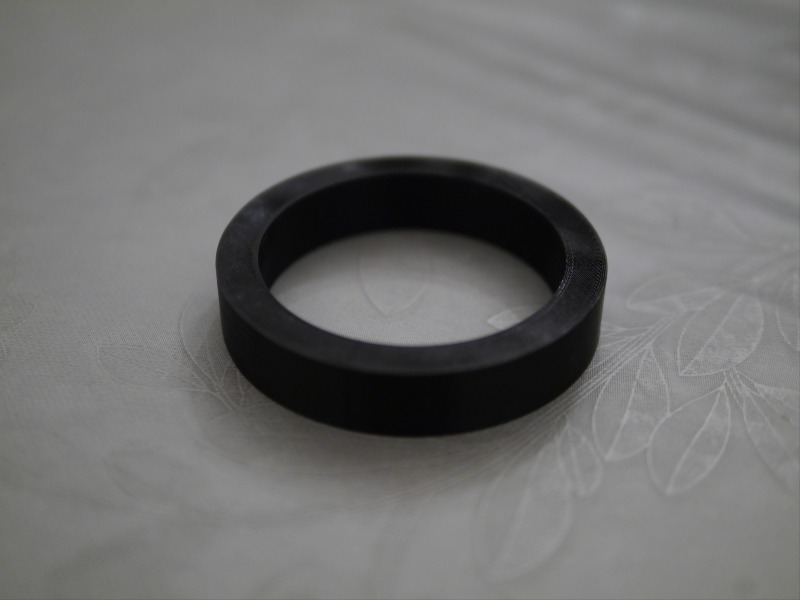
In the meanwhile I have printed the ring in the back left corner and back right corner with the same result as before. The helix appears on the left back side of the ring (see red lines below) regardless of the placement on the print bed. With no negative pattern on the other side. Given your theory is right shouldn’t there be a corner with a stronger and one with a weaker effect? Is there a way to fix or compensate the issue you described to see if it gets better?
Rotation of the mount, not translation in the case of backlash. Like, the front or side of the platform moves up and down as it changes direction, or the toolhead moves side to side or. up and down
Because of the small angle deviation from 90 and relative unimportance of the true reading, you don’t have to get it perfectly orthogonal. Eyeballing it will be good enough. For this measurement some duct tape would mount it well enough as long as it doesn’t move.
Even it you mounted it at 20 degrees off it would still take a reading of variation just fine, just each tick mark on the indicator would not equal 0.001"
That’s probably true, I’ll have to stew on that.
Mostly just trying to come up with ideas that could induce a repeating pattern. Pretty much rules out the controller.
The period you mentioned of ~1.8mm is like ~1/4 turn of the Z module lead screws, which doesn’t really make sense to me as being an explanation. Trying to come up with something else that would induce something like this.
I don’t think I’ve seen anything else like this on the forum before.
I took 4 readings each on X and Y as straight moves (circles are a bit tricky on the touch panel).
Going outside from the center / stepping 1mm further and back again:
Left: -0.001mm / -0.001mm
Right: 0.034mm / 0.045mm
Back: 0.002mm / 0.023mm
Front: 0.000mm / 0.000mm
There seems to be some wobbling on both axis. So what would be the next step?
I made a second test stepping out 50mm to the outside first. Then another 10mm and 10mm back again. At the center the value changed probably because the tape didn’t hold tight enough. Therefore, only the value in one line can be compared with each other. The previous wobbling effect got stronger due to the longer movement…
Left: 0.155mm / 0.024mm
Right: 0.024mm / 0.047mm
Back: -0.022mm / 0.014mm
Front: 0.172mm / 0.168mm
It would be interesting to hear from others if they have also noticed such an issue. Re-evaluating my old prints I found that this not just happened recently to me.
I did not notice it at first but there is actual a difference in the pitch of the helix depending on the print bed position (the bottom of the part is on the right side). Does that assists your theory @brent113?
I don’t think so, I think it would have to be something else. Struggling to come up with something plausible though.
Could this be related to bed levelling? Left back and center are more similar than right back, which appears to be the same relationship as your bed levelling mesh - right back is different than left-back and center which are similar.
I do not think so. I did another print at the right center to make sure. This looks very similar to the back right one. The pitch gets smaller on the left side and wider on the right side. No idea how much the back/front position adds to this though.
@Tigercjn definitely worth a shot, I’ve seen weird stuff be caused by slicers for sure.
@dstarke have you tried a different slicer? I know Cura has a ton of settings and am curious if one inadvertently got messed up without knowledge of it happening.
It is hard to believe that this is a slicer issue since this is a very trivial object, the issue changes depending on the bed position and no one else on the internet seems to have such a problem. But sure, I will give it a try after the current print is done (maybe tomorrow).