Alright, this guide is going to be a bit more quick and dirty than my other guides, since it’s mostly a setup and has a lot of variables you can play with. I’ll try to supplement with pictures though!  Keep in mind, this moves milling to the lower left of the work platform, due to the lack of rigidity, may present issue on deep/stressful cuts that apply enough pressure to deflect the surface. However most work shouldn’t be affected. A lot of things are out of the scope of this guide, I take liberties in your knowledge of the snapmaker, such as changing bits, using the control panel to jog around, setting the origins individually, and other such nonsense. However, as always, you can ask and either I, or someone else will do our best to help. This is somewhat a guide for those wanting to move up with their milling projects outside of just reliefs or text carving. The main use of this is for accuracy, and if you want tool changes, but are milling the entire face and can’t re-reference the top of the material.
Disclaimer: I am in no way responsible for any possible damage to your machine or materials, although risk is very minimal if you follow along exactly as I am going to include images of my settings, setup, and results. Please read the entire guide before attempting.
Materials and Machinery in this tutorial:
Snapmaker A350 + Enclosure
Tools: 3.175mm (1/8") 2-flute down-spiral flat end mill for roughing; 0.75mm Radius Tapered Ballnose for finishing.
Material: Maple Plywood - 228.6mm X 228.6mm X 19mm (9" x 9" x 3/4")
Model to be machined: 9 Frame by alexlopreciado found here: Download free STL file 9 FRAME • Object to 3D print ・ Cults
Prerequisite Print: CNC Guide Rails found here: PrusaPrinters
Optional Print: Dust Fence: PrusaPrinters
I: Preparation
1: Print the guide rails, I’ve included the gcode I used on the print page. Use M4x16 to attach them to the spoilboard.
1a: You can also use the optional dust fence for the other side to help contain the dust to the platform for easier cleanup.
2: Use any preference of clamping method, I used these to press against the guide rail: https://www.thingiverse.com/thing:4644169 nice and low profile to stay out of the way, and let me CNC the entire surface.

II: Finding the Work Origin
1: Load in a straight bit you know the diameter of.
1a: I’m using a 3.175mm for my roughing, so it was what I already had in. Keep in mind the size of your bit, as we’ll be using that math later.
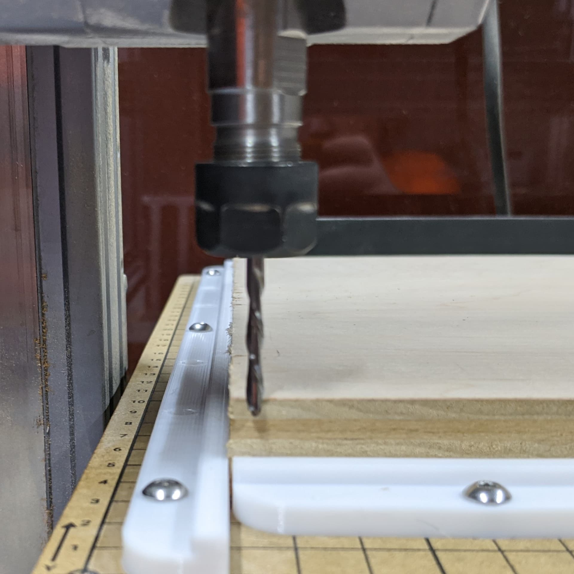
2: Locating X origin
2a: Carefully lower the bit down to the left of the material, then slowly move it against the side using the calibration card.
2b: When you feel resistance, jog Z up higher than the material.
2c: Divide the diameter of your bit by 2 to find the radius (3.175/2 = 1.5875). Jog toward the material (X positive) 0.1mm to compensate for the calibration card, then the radius of your bit (since the snapmaker limits manual control, I use 1.6mm here).
2d: The center of your tool should be directly over the edge of the material.
2e: On the control screen, go to the set origin tab, set X origin.


3: Locating Y origin
3a: Repeat 2a-2e, but from the front of the material.
3b: Set Y origin on the control screen.

4: Locating Z origin
4a: Use the normal method of setting the Z origin by moving the bit over the material and jogging down on the calibration card
4b: Set Z origin on the control screen.

5: Raise Z up and then tap “Go to Work Origin” it should move down directly over the lower left corner of the material.


III: Repeatable Origin
1: Take a picture of the control screen, unless you remove the rails, or change the machine to another function, this origin should remain the same and can be moved back to.
1a: This takes care of the eyeballing it on an “X” in the center of the material, and also allows you to utilize your material more effectively by knowing exactly where your bit will be.
2: If you’re doing multiples of the same project, this gives you a lineup and re-setup for finishing passes.
3: Z axis for bit changes will be covered in a later section.
4: If you want to center on your material, take your stock size and divide it in half, then move X/Y the result and set Origin.
4a: If you do this, you can skip section IV to change the work coords and use the same center method you’ve always used.
IV: A Side Note For CAM (Example In Fusion360)
1: You will have to make a note of the new work origin when you assign toolpaths to your model.
2: In your Fusion360 setup, in the stock tab you can either use a relative size, set your stock size to fixed, etc.
2a: Since I made my model the exact size of my stock and engraving from the top, I used relative with 0 offsets, making my stock the same size of my model.
2b: Setting up stock is outside of the scope of this guide, but if you need help, feel free to post and I’ll try to help.
3: The most important part here is the first tab, setup.
3a: Set your Origin to the top, lower left, this corresponds to where we put the bit earlier.
3b: If you forget to change from center, your model will be centered over the lower left of your material when you try to cut it.

V: Z, The Special Child of Origins (How To Repeat For Changing Tools)
1: There’s two main methods for ensuring Z is repeatable for roughing/finishing after bit changes.
1a: The first method is the one I’ll be walking through here, it’s best for engraves and cuts that need a definite depth from the face.
1b: The second method is harder to wrap your head around and makes the program setup more important, however, it’s a lot better for parts with through-cuts and is common in commercial CNCing.
2: Finding the thickness of your material
2a: Since you set the bit down on the top of the material, we’ll measure down to the spoilboard to use this depth later.
2b: Move the bit down to the front similar to setting the Y axis, but make sure to be over the MDF.
2c: Jog down and use the calibration card to gently touch down to the spoilboard.

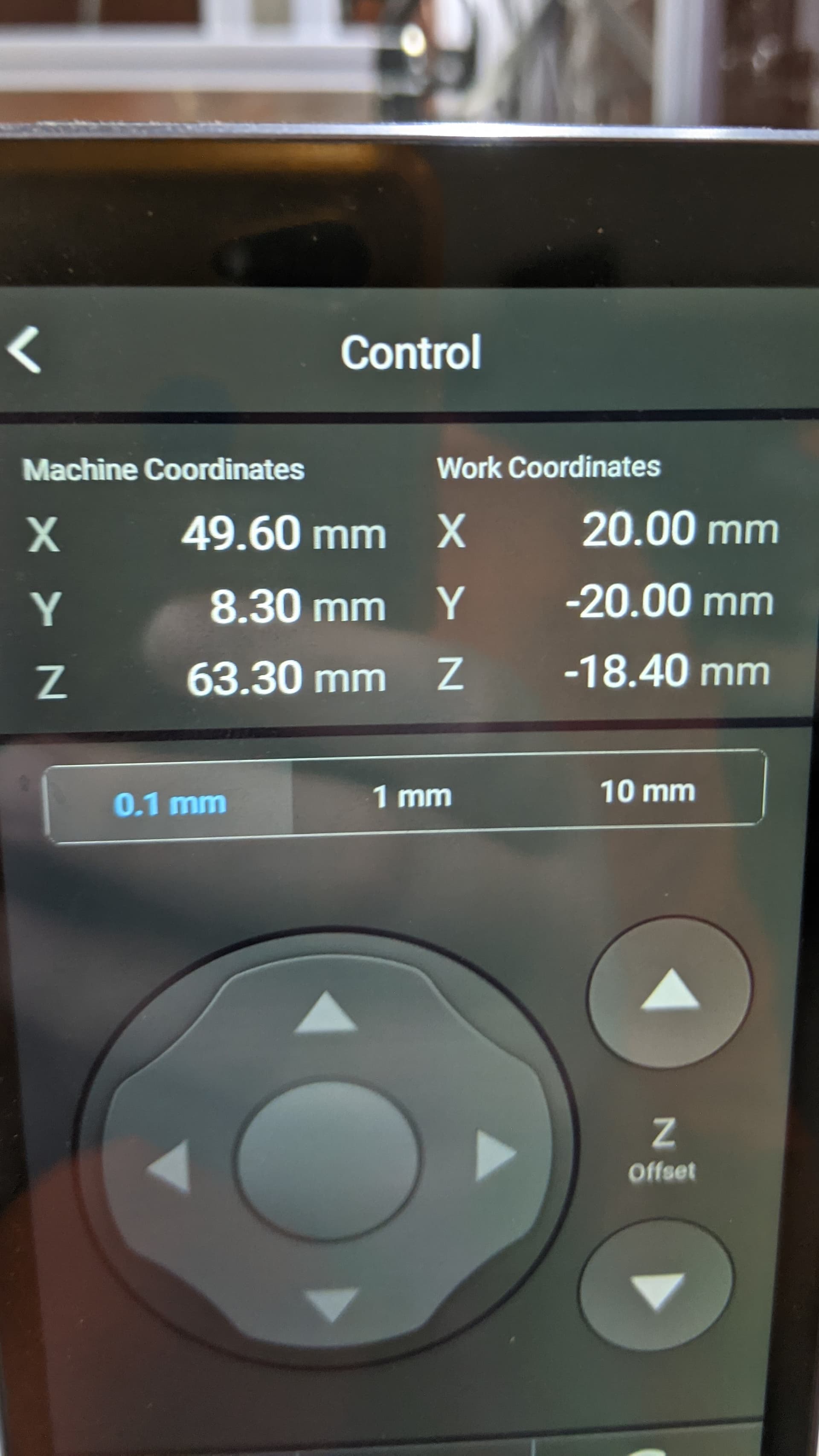
2d: On the control screen take a picture or write down the Z-, DO NOT SET Z ORIGIN, JUST NOTE THE DISTANCE.
2e: This number is the thickness of your material that we have to return to later. (Mine was Z-18.40)
2f: JOG Z BACK UP, if you try to go back to origin while the bit is lower than the material, you risk breaking it by crashing into the material.
3: Run your roughing pass as usual
4: Change your tool for your finishing pass.
5: Follow 2b-2d, except this time, SET Z ORIGIN.


5a: Jog Z back up the exact same distance (material thickness) we found earlier, except in the positive direction. (Mine was Z18.40)
5b: SET Z ORIGIN AGAIN.
5c: What we did here was use the spoilboard as a reference point so we could use that point to find the top of our material, even if you’ve milled it entirely.


(Tch, finish depth was at a layer change, shame. Not bad for a test though.
 )
)
VI: The Second Method (Do Not Use This Unless You Are Experienced, Which Means You Already Know It)
1: Instead of using the traditional method of setting Z0 to the top of material and all cuts are Z- X distance, we somewhat ignore the stock entirely.
2: The Z0 will actually be on the spoilboard and all cuts will be a Z+, since Z0 will be the lowest it goes, it guarantees you will not cut through the spoilboard, and ensures you can cut all the way through.
3: This also makes bit changes easier since you’re always setting Z back to the spoilboard, no having to back up the material thickness, especially since stock can be different depending on how they were manufactured.
4: NEVER USE “GO TO WORK ORIGIN” OR YOU WILL RAM THE BIT INTO THE MATERIAL.
4a: This is because Z0 is the spoilboard under your stock.
5: The main difference here is the con; you lose a lot of safety tests (i.e. go to work origin) to double-check things, and have to ensure your setup and work is correct before moving on.
5a: Pro; You get a lot more repeatable setup, and can even make the stock size a bit irrelevant as long as you have the torque to pull it off, and you get a lot more life out of the spoilboard by not accidentally cutting too deep.
6: In your CAM program you will have to setup a fixed stock to match your material.
6a: If you’re doing an engrave, set your model to be offset 0 from the top of stock.
6b: In the setup tab, make your origin point the BOTTOM at the lower left.
7: This is only really good for commercial practice when cutting all the way through, you can use the same setup for any material thickness (i.e. use the same program to make a 1/4" template, then a 3/4"+ product) since it always cuts down to 0 instead of Z- from the material surface.
7a: This also helps ignore inconsistencies in material manufacture, I’ve had plywood thickness vary up to 1/16" across 24" width.
7b: This is also good for surfacing material if you need a specific thickness before milling.
7c: This method usually requires a more rigid machine than the Snapmaker, since the platform has a bit of play it’s not precise.
VII: Prologue And Thoughts
So much for short, but anyway, there’s a ton of uses for this, especially having a dedicated origin. Since you always know where your bit is in relation to your stock, you can use it more effectively. An example would be for a simple cut, like a logo carve, keychain, or other small object. You could load up a larger piece of stock, run it once to make sure it works, then jog around to ‘stamp’ it in the material, especially if it requires cutting all the way through and standard clamping wouldn’t work on the small object. Or if your model needs to be in an exact location instead of centered, you can simply do the math and move it anywhere. Just knowing your start point helps so much. Go carve something neat.
Once this test is done, I’ll post an update. 


