After some programming sessions with Blender and Python I have now a first result, so if anyone is interested, here it is.
This is a Python script which needs Blender (currently 4.2). In Blender there is a top menu “Scripting”, there a new Text file can be created, this script inserted and then the script can generate hulls on 3D objects.
This is the script:
import bpy
import os
from mathutils import Vector
import bmesh
import math

# --------------------------------------------------------------------------------------
class Settings:
    def __init__(self):
        self.OFFSET_MM = 6  # Abstand in mm
        self.TOOL_DIAMETER_MM = 3  # Fräserdurchmesser in mm
        self.TOLERANCE = 0.0001
        self.NUMBER_OF_RINGS = 50
        self.SHORTEN_CYLINDER_MM = 0.1

# --------------------------------------------------------------------------------------
def show_message_box(message="", title="Message Box", icon='INFO'):
    # draw ist eine Callback-Funktion, die Blender aufruft
    def draw(self, context):
        self.layout.label(text=message)

    print(message)
    bpy.context.window_manager.popup_menu(draw, title=title, icon=icon)

# --------------------------------------------------------------------------------------
def delete_all_except_camera_lights():
    # Löscht alle Objekte außer Kamera und Lichtquellen
    for obj in bpy.context.scene.objects:
        if obj.type not in ['CAMERA', 'LIGHT']:
            bpy.data.objects.remove(obj, do_unlink=True)

# --------------------------------------------------------------------------------------
def get_max_distance_from_origin(obj):
    max_distance = 0
    for vertex in obj.data.vertices:
        co = obj.matrix_world @ vertex.co
        distance = math.sqrt(co.x**2 + co.z**2)
        if distance > max_distance:
            max_distance = distance
    return max_distance

# --------------------------------------------------------------------------------------
def get_object_center(obj):
    min_x = min_y = min_z = float('inf')
    max_x = max_y = max_z = float('-inf')

    for vertex in obj.data.vertices:
        co = obj.matrix_world @ vertex.co
        min_x = min(min_x, co.x)
        min_y = min(min_y, co.y)
        min_z = min(min_z, co.z)
        max_x = max(max_x, co.x)
        max_y = max(max_y, co.y)
        max_z = max(max_z, co.z)

    center_x = (min_x + max_x) / 2
    center_y = (min_y + max_y) / 2
    center_z = (min_z + max_z) / 2
    return (center_x, center_y, center_z)

# --------------------------------------------------------------------------------------
def center_object_to_origin(obj):
    center_x, center_y, center_z = get_object_center(obj)
    obj.location.x -= center_x
    obj.location.y -= center_y
    obj.location.z -= center_z
    bpy.ops.object.transform_apply(location=True)

# --------------------------------------------------------------------------------------
# Äußeren Zylinder erstellen
def create_outer_cylinder(obj, offset, side_length):
    # Berechne die maximale Entfernung eines Punktes vom Ursprung in X-Z-Ebene
    max_distance = get_max_distance_from_origin(obj)

    # Berechne den neuen Radius mit dem zusätzlichen Abstand
    new_radius = max_distance + offset

    # Berechne die Anzahl der Seiten
    circumference = 2 * math.pi * new_radius
    num_sides = round(circumference / (side_length * 0.9)) # 90% der Breite des Fräsers

    # Länge des Objekts in der Y-Richtung übernehmen
    height = obj.dimensions.y - 2 * stng.SHORTEN_CYLINDER_MM

    # Zylinder erstellen und ausrichten
    bpy.ops.mesh.primitive_cylinder_add(vertices=num_sides, radius=new_radius, depth=height, location=(0, 0, 0))

    # Zylinder um 90 Grad um die X-Achse rotieren, damit er entlang der Y-Achse ausgerichtet ist
    cylinder = bpy.context.object
    cylinder.rotation_euler[0] = math.radians(90)

    bpy.ops.object.transform_apply(location=True, rotation=True)

    return cylinder

# --------------------------------------------------------------------------------------
def get_relevant_edges(obj):
    """Holt vom erstellten Zylinder nur die
    Kanten, die den Zylinder darstellen,
    nicht die, die Boden und Deckel beschreiben

    Args:
        obj (Mesh-Objekt von Blender): Ein Standard-Zylinder-Objekt von Blender

    Returns:
        list: Eine Liste der relevanten Kanten
    """
    relevant_edges = []
    for edge in obj.data.edges:
        start_point = obj.data.vertices[edge.vertices[0]].co
        end_point = obj.data.vertices[edge.vertices[1]].co

        # Nur Kanten mit Y-Ausdehnung ausgeben
        if abs(start_point.y - end_point.y) > stng.TOLERANCE:
            relevant_edges.append((edge, start_point, end_point))

    # Sortiere die Punkte in jedem Edge-Tupel basierend auf ihrem Y-Wert
    sorted_edges = []
    for edge, start_point, end_point in relevant_edges:
        sorted_points = sorted([start_point, end_point], key=lambda point: point.y)
        sorted_edges.append((edge, sorted_points[0], sorted_points[1]))

    print(sorted_edges)
    print(len(sorted_edges))

    return sorted_edges

# --------------------------------------------------------------------------------------
# Funktion zur Ermittlung der Verteilungspunkte
def get_distribution_points(relevant_edges, num_distribution_points):
    """_summary_

     Args:
         relevant_edges (_type_): _description_
         num_distribution_points (_type_): _description_

     Returns:
         _type_: _description_
    """
    distribution_points = []
    for edge, start_point, end_point in relevant_edges:
        points = []
        for i in range(num_distribution_points):
            factor = i / (num_distribution_points - 1)
            point = start_point + (end_point - start_point) * factor
            points.append(point)
        distribution_points.append((edge, points))

    return distribution_points


# --------------------------------------------------------------------------------------
# Funktion zur Ermittlung der Schnittpunkte
def get_intersection_points_all(distribution_points, inner_obj):
    """_summary_

     Args:
         distribution_points (_type_): _description_
         inner_obj (_type_): _description_
    """
    intersection_points = []
    for edge, points in distribution_points:
        for point in points:
            origin = point + Vector((0, stng.TOLERANCE, 0))
            direction = (Vector((0, point.y, 0)) - origin).normalized()
            result, location, normal, index = inner_obj.ray_cast(origin, direction)
            if result:
                intersection_points.append((edge, Vector(location), point))
            else:
                print(f"Ray casting missed at point: {point} on edge: {edge.index}")

    return intersection_points

# --------------------------------------------------------------------------------------
# Kürzen der Linien aktualisieren
def shorten_lines_all(intersection_points, cylinder_obj):
    # Neues bmesh für den Zylinder erstellen
    bm = bmesh.new()
    bm.from_mesh(cylinder_obj.data)
    short_points_all = []  # Liste zum Speichern aller "short points"

    for edge, location, point in intersection_points:
        # Berechne die Weltkoordinaten der Schnittpunkte und Startpunkte
        world_location = cylinder_obj.matrix_world @ location
        world_point = cylinder_obj.matrix_world @ point

        # Richtung vom Schnittpunkt zum Punkt berechnen (Vektor in Weltkoordinaten)
        direction = (world_location - world_point).normalized()

        # Endpunkt 2 mm vom Schnittpunkt nach innen verschieben
        short_point_world = world_location - direction *  stng.OFFSET_MM  # Abstand zu Modell, Linien kürzen

        # Konvertiere den gekürzten Punkt in die lokalen Koordinaten des Zylinders
        short_point = cylinder_obj.matrix_world.inverted() @ short_point_world

        # Erstelle die Kante mit dem Startpunkt und dem gekürzten Endpunkt im bmesh
        start_vert = bm.verts.new(point)
        end_vert = bm.verts.new(short_point)
        bm.edges.new((start_vert, end_vert))

        short_points_all.append((edge.index, short_point))

    # Aktualisiere das Mesh mit den neuen Kanten
    bm.to_mesh(cylinder_obj.data)
    bm.free()

    return short_points_all

# --------------------------------------------------------------------------------------
def create_edges_from_points(short_points, num_distribution_points):
    bm = bmesh.new()

    # Gruppiere die Punkte nach Edge-Index
    points_by_edge = {}
    for edge_index, point in short_points:
        print(edge_index)
        if edge_index not in points_by_edge:
            points_by_edge[edge_index] = []
        points_by_edge[edge_index].append(point)

    # Edge-Indices sortieren, um Konsistenz sicherzustellen
    edge_indices = sorted(points_by_edge.keys())
    num_edges = len(edge_indices)

    for i in range(num_edges):
        edge1_points = points_by_edge[edge_indices[i]]
        # % num_edges: Um beim letzten Edge wieder beim ersten Edge zu verbinden
        edge2_points = points_by_edge[edge_indices[(i + 1) % num_edges]]

        for j in range(len(edge1_points) - 1):
            v1 = edge1_points[j]
            v2 = edge1_points[j + 1]
            v3 = edge2_points[j + 1]
            v4 = edge2_points[j]

            vert1 = bm.verts.new(v1)
            vert2 = bm.verts.new(v2)
            vert3 = bm.verts.new(v3)
            vert4 = bm.verts.new(v4)


            bm.faces.new((vert1, vert2, vert3, vert4))
#            # Linien statt Faces erzeugen:
#            bm.edges.new((vert1, vert2))
#            bm.edges.new((vert2, vert3))
#            bm.edges.new((vert3, vert4))
#            bm.edges.new((vert4, vert1))

    # Neues Mesh erstellen
    mesh = bpy.data.meshes.new("HullMesh")
    bm.to_mesh(mesh)
    bm.free()

    # Neues Objekt für das neue Mesh erstellen und zur Szene hinzufügen
    obj = bpy.data.objects.new("HullObject", mesh)
    bpy.context.collection.objects.link(obj)

    return obj


# --------------------------------------------------------------------------------------
# --------------------------------------------------------------------------------------
# --------------------------------------------------------------------------------------
def main():

    # Aktives Objekt abrufen und zentrieren
    obj = bpy.context.active_object
    center_object_to_origin(obj)

    # Äußeren Zylinder erstellen    cylinder_obj = create_outer_cylinder(obj, stng.OFFSET_MM, stng.TOOL_DIAMETER_MM)

    # Aufruf der Funktionen und Debug-Ausgabe
    relevant_edges = get_relevant_edges(cylinder_obj)

    distribution_points = get_distribution_points(relevant_edges, stng.NUMBER_OF_RINGS)

    intersection_points = get_intersection_points_all(distribution_points, obj)

    short_points = shorten_lines_all(intersection_points, cylinder_obj)

    create_edges_from_points(short_points, stng.NUMBER_OF_RINGS)

    # Lösche das Objekt
    bpy.data.objects.remove(cylinder_obj, do_unlink=True)


# --------------------------------------------------------------------------------------
if __name__ == "__main__":
    # Systemkonsole leeren
    os.system('cls')  # Konsolenausgabe löschen

    stng = Settings()  # Instanziierung der Konstanten

    # Überprüfen, ob mindestens ein Objekt ausgewählt ist
    if bpy.context.selected_objects:
        main()  # Hauptfunktion aufrufen
    else:
        show_message_box("Kein Objekt ausgewählt. Bitte wähle ein Objekt aus und versuche es erneut.", title = "Fehler", icon="ERROR")
At the beginning in the class Settings the parameters can be changed.
OFFSET_MM is the distance between the hull and the STL model.
TOOL_DIAMETER_MM don’t need an explanation  The hull is created with a cylinder around the object and 90% of width of the diameter is used for the number of cylinder faces.
NUMBER_OF_RINGS: The number of positions on the cylinder used to test the height of the model at this place. With 10 it would be a rough hull, with 200 a finer. The more rings, the longer the calculation.
TOLERANCE should not be changed.
SHORTEN_CYLINDER_MM: The cylinder around the model is shortened at both ends by this value. This makes sure that the first and last ring lands on the STL model.
After setting the parameters this is the way it works:
Load a STL model and align it to the world’s Y-axis (as this is the axis you also use later in snapmaker). The position doesn’t matter, it will be aligned to 0/0/0 later.
Set the size in a way that fits to the final size of the model when using it in the rotary module. That can be done by clicking on the object properties (orange square with orange brackets in the vertical icon row on the right side) and use “Scale X/Y/Z” to scale it until it fits.
Important step: After doing that, make sure the object is selected, click CTRL-A and use “Scale”. This resets the Scale to 1/1/1 and saves the current model size in the szene to the new scale. Otherwise it cannot be measured with Python.
When importing the STL-object, look in the file dialog at the right side, there also should always be a scale value of 1.
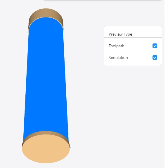
And then - just select the object and in the Scripting at the top of the text editor there is a “play” button. Click it and you’re done. You see the new hull object around the model, depending on your setting more or less detailed.
Check the hull against the model being inside if nothing goes through the hull object. That can happen if you choose too less rings and the model has a lot height differences. Increase it until the hull does not touch the model. So this is now your roughing model which you can make with a bigger tool instead of the tiny tools of Snapmaker. This can be setup with rough stepping and going deeper at the first try, depending on your tool. But you can get 6mm diameter tools into the machine, so for this size very much bigger heads exist which will not break.
The hull generator works also on the hull object. So if you select the generated hull you can generate the next around this with another distance and detail grade. So it’s also possible to work on material which is bigger to take away the rough parts without waiting years to let the V bit doing it…
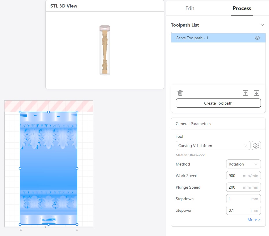
The generated hull can be exported as STL and imported to Luban.
Using a heightmap is in my eyes way to inaccurate to use it as there is no exact positioning possibility in Luban and in my tests I often see seams in the preview results in Luban - that’s not good enough. So I’m afraid, only Luban itself can generate exact height maps when using an STL file. I’ve tried several heightmaps importing but Luban then also wants to have the depth and so on - maybe OK for 2D reliefs, but not for rotary models with exact output.
Next I’m trying to generate GCode from Blender with Python. The first fast shot was not bad, but inserted to much model details. But the result in Luban was surprisingly very exact the representation of what was generated. So it’s possible and I’ll try to get it work.
Result should be to have a method to first remove the undetailed material and then be faster and more secure for the fine tool to do the detailed work. I also found a GCode which makes it possible to wait on a click on the screen so maybe a tool change between this and the detail run should also be possible.
Maybe it’s useful for someone!
