Hi,
Please check out this post and see if at applies to your situation: Working camera capture with Lightburn - #30 by Mayco.
If not, please let me know and I’ll try to reproduce the problem on my side.
Hi,
Please check out this post and see if at applies to your situation: Working camera capture with Lightburn - #30 by Mayco.
If not, please let me know and I’ll try to reproduce the problem on my side.
Thanks for the answer. I was able to move it to the desired coordinates.
I see that homing on the touch screen and G28 are two different things. When I input G54 after homing on the touch screen, I could not move to the desired position.
I would have liked to see it stated in the manual that G28 and G54 are required.
I have managed to capture images at the desired location, but I am unable to display them correctly with the proper scale in the left side work area of the Lightburn screen. Do I need to perform Calibration Camera Alignment for this? I tried it, but it didn’t work well.The head collided with the bed, and I hastily turned off the power.
In calibration, which option should I also select for the camera mounting position and other options?
What I want to do is place the drawing to be cut with the photo as a background.
Once saved as an nc file, I will transfer the file in Luban.
Could you please tell us about the work procedure?
After camera lens calibration is done, you have to perform the alignment. For this you need to define the camera as “fixed” (it’s effectively fixed at the position defined in your config file).
As for exporting as NC and transferring via Luban: I run my laser jobs straight from LightBurn over serial connection as this gives LightBurn full control. Luban or the Snapmaker touchscreen firmware might inject some unwanted GCode before running the job, so I prefer not the go that route.
Perhaps others in this thread have experience with running the job from a file.
When the Start button was pressed on this screen, the laser module crashed into the bed.
What we did was.
1.touch screen homing
2.G28,G54
3.XY coordinate adjustment (Frame check)
4.Moved Z coordinate to around 40
5.Start
I think it was.
Can you post a screenshot of all your settings in “device settings”?
@Mayco maybe a feed speed setting would allow the movement to be slowed when first testing setup. I am equally slightly afraid of lightburn due to it doing things it’s way, and potential for collisions (they can happen with luban too).
I wanted to set this up tonight, but think I can only afford to have a go when I’m less tired. I’ve noticed the two gcode commands to be run from terminal, and about installing softcam, and the github releases page, so think it’ll be fine ![]()
While it’s certainly an option to make the feedrate a setting, the tool will not move your laser anywhere near the bed unless you specifically tell it to do so using the config file. The collision seen by @ViperZ is most likely caused by other incorrect settings in LightBurn.
I highly recommend following the guide from @Skreelink (Full Lightburn Control Guide) to set up LightBurn correctly, and then try to use this software.
Really appreciate the advice. I’ve used it for the odd thing fairly successfully, but was well aware workspace coordinates screw the game as do certain other commands (change coords without user realising). Not used it in months as luban got better, but want to come back and just installed 1.400
The content of the device settings is as follows.
Other things I tried and found out.
After powering on the SM2, when G28 and G54 were set, the coordinate values were as follows.
After homing using the touch panel following the power-on of the SM2, sending G28 and G54 resulted in the following coordinate values, allowing the machine to move to the desired location and perform the capture.
Is homing on the touch screen required?
It may be required, I would have to confirm. It is usually part of my routine to perform the first homing action via the touchscreen when the printer is powered on. However I don’t know the exact GCode it emits.
I would also suggest you follow the LightBurn guide from @Skreelink (Full Lightburn Control Guide) first. The “Start GCode” of your device settings should contain GCode that sets the Z-axis correctly.
The snapmaker seems to have some form of check built in that requires at least one homing command done through the HMI interface. Be it either the touchscreen, luban, or the web API. I normally just wait a few moments for the machine to fully boot and enter the control screen on the touchpad before walking away. Failing that, I’ll pop open my code sender and just send a G28 from there, which uses the web API like Luban does, so it sets the “all ready” flag in the machine.
Thank you for the advice. I am now able to do laser engraving with Lightburn.
The reason for the collision of the head with the bed was because the “relative Z moves only” switch was turned off. It could be possible that this happened because I hadn’t set up the Start GCODE, but I haven’t verified it yet.
I haven’t performed Skreelink’s custom firmware and XY correction yet, but it has become incredibly convenient to be able to layout and laser engrave based on the captured photos.
That’s great! Indeed I had a vague memory of a setting that influenced Z moves but I couldn’t remember it, good that you found it. I also don’t have the custom firmware (currently on the vibration compensation firmware for printing), but I’m happy with the LightBurn setup as-is.
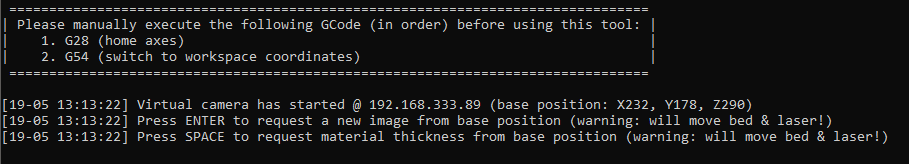
I have an idea that I would like you to consider. The camera’s shooting coordinate (Z-coordinate) is currently specified in the Config, but I would like it to be possible to specify it at runtime. If the user only presses the Enter key, the camera will capture at the Config-specified position. However, if the user enters ‘1’, ‘0’, ‘.’ , ‘3’ and then presses Enter, the camera will capture from a position 10.3mm above the Z-pos set in the Config. This will allow for adjusting the placement of the design to accommodate changes in material thickness. Well, probably…
When cutting MDF, raising it slightly off the work surface reduces the likelihood of resin sticking to the backside. However, this caused a concern of increased misalignment in the resulting image.
I tried modifying and running the source code of SnapmakerLightburnhost.
Let’s combine this with the automatic thickness measurement. We just need to make sure that the z axis cannot be lifted to infinity xD
Thanks for this. Are you also defining the Z-height of your material in Lightburn?
In my case, the object being measured may not necessarily be located in the center of the workspace. Additionally, the thickness of the work material is mostly fixed at 10mm. It would be more convenient for me to separate the functionality.