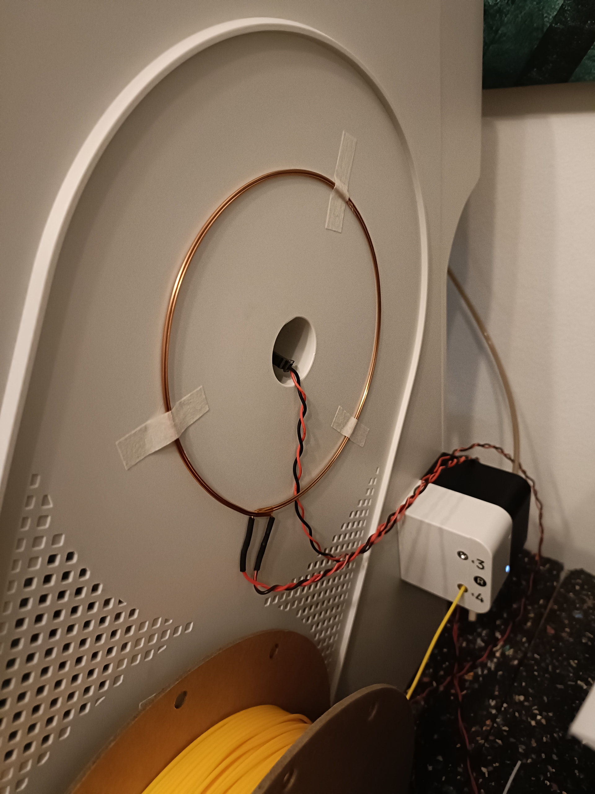
I simply don’t have enough space to run the U1 with the side spools and feeder attached on the sides but I’d still like to use the feeders and RFID filament recognition. I have a Ikea Bror Shelf setup with spool rollers in boxes for 4 filament spolls on top and I’d like to put the U1 in there but like I said there is not enough space for the feeders and spools on the sides.
As a first step I tried to extend the wires of the RFID coils to maybe 1 meter. The connectors btw are JST-GH 1.25 2pin ones. I just soldered them off the coils and soldered on longer cables with a microfit connector on the other side. The original cables also received microfit connectors.
I made sure to solder them on the correct ends of the coil and fitted them outside the side panels in the correct direction just for a test. I also checked + and - of the plug and there is continuity like expected. Unfortunately now the filament recognition doesn’t work anymore
Any ideas why and how I may get them to work with longer cables? I had one reply over at discord stating that the cables resistance and capacitance is probably something that is tuned with components on the board, so changing the length might “detune” the coils..
Any ideas if I can solve that somehow? Maybe tweak a value in software? Or somehow amplify the coils?
Nice project, I like! Just to understand (I do not own a U1, cannot look myself): The coils we see are the original coils from the printer, just moved to the outside? I’m surprised how large they are, how thick the wire is and how few windings they have. On the other hand… if you look at standard NFC reader modules for Arduino, the PCB coils do not have many more windings…
That said, typical NFC/RFID chips work at 13.56 MHz, and this frequency may require a shielded coaxial cable for longer distances (not really an expert, take with a grain of salt! but this page: Produkte: RFID Antennen – ubisys RFID seems to support my assumption).
Do you perchance own or have access to an oscilloscope? You could compare the signals from an unmodified antenna to your modified one. If the cable is the problem, I suppose you’d see the deterioration of signal quality.
Yes, these are the original coils, just moved outside for testing purposes.
Interesting idea, I didn’t think of that, since the short ~ 20cm original cables also didn’t have any shielding. I have cat5e lan cable at hand, first though I’ll fabricate new short,”stock” cables again, just to rule out any other errors on my end.
Unfortunately I don’t have an oscilloscope, tbh I wouldn’t know what exactly I should compare I’m an electronics noob, but maybe it’s time to get an osci.
Regarding what you would see on the oszi: RFID works with “parasitic” data transfer, i.e. the coil emitts a magnetic field with said 13.56 MHz frequency. The RFID chip uses this to harvest a tiny bit of energy to power the chip, and then it changes its receiver to draw more or less energy from the magnetic field, encoding 1s and 0s by different levels of power draw. The RFID antenna/circuit of the RFID interface will register these variations and translate them into binary code. With the oszi I’d suppose you’d see variations in the amplitude of the 13.56 MHz signal (my assumption, never checked myself - found this: A Universal RFID Key : 9 Steps (with Pictures) - Instructables that seems to support my assumption).
I don’t know specifically for this antenna, but I have done antenna tuning in general. Indeed if it’s a resonant design, then changing the lead length may cause it to become insensitive to the specific pickup frequency.
You can get USB oscilloscopes for pretty cheap these days. You no longer need a $10,000 fluke ‘scope. Just make sure it can more than 13.56 MHz. So not a $20 scope, but a $100 scope looks like it’ll do you.
Even if you’re not a electrical engineer, that’ll likely give you some information. If the original outputs a 13.56MHz signal, and your modified one is a different frequency, then you have an answer to the “Why?”. The “How to fix?” will require some more work, but I’m not qualified to help you there. I took one look at the syllabus for the RF and Power propagation class, and decided that I’d rather be a Computer Engineer and design processors. I remember both resistance and capacitance being involved, but none of the details. Or was it resistance and inductance…
Thx for the info about oscillosocpe. I wish I had more time and motivation at the moment to look into that as the whole thing sounds interesting. I received connectors for jst gh1.25 yesterday, so I can try out different cables, plugs and lengths. Maybe also the microfit plug I added is not ideal, but I need a way to quickly unplug everything to get the printer out for maintenance.
I hope the feeders can be extended without the same hassle, I already ordered 1m long 15pin cables that should fit…. but I’ll still need some way to quickly plug/unplug them…maybe some small pcb that has two female jst gh1.25 15pin connectors on it.
Yes. The feeders should be more trivial so long as the connectors are good and it’s not a super long cable that degrades it too much or picks up interference.
So I did some testing today with shorter cables and cat5e cable. The longest I was able to extend the default ~20cm cables was +40cm….so too short for my use case. I need min. +80cm. It made no difference if I used normal cable twisted, or cat5e cable.
I don’t think I’m able to retune the frequency, I have no oscilloscope and I don’t plan on soldering capacitors on the mainboard or the left extension board.
What do you think, is it worth trying such rfid antenna cable like @Hauke mentioned? Or am I out of luck here?
Could I maybe solder sth. in between the wires? If I understood correctly it needs to be sth. that reduces capacity since the longer cables likely add more capacity themselves.
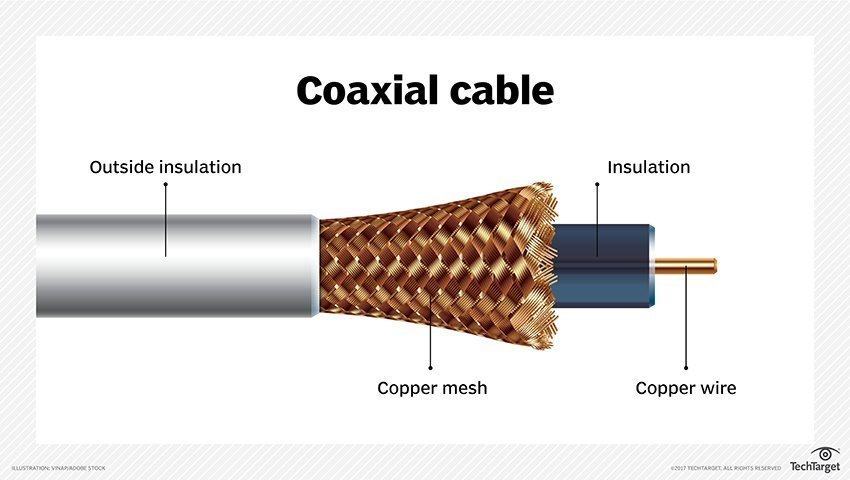
Someone made the point that you need to use something like coaxial cable, not cat5/6. Huge difference in shielding! Whether they helps you or not, I can’t answer but if you can find coaxial you need to try that before giving up…
I think there’s a good chance that the coaxial cable will do the trick - these cables are made for high frequencies and have the necessary electrical characteristica. However, they may require additional components to avoid reflections of waves at the cable ends - usually 2 resistors, one at each cable end, matching the cable’s impedance, so typically 50 or 75 Ohm). But I say this with only half-knowledge, not really as an expert. If I were you, I’d give it a try, these cables do not cost too much. The one I linked above is long and has connectors at its end - the “raw” cable is single-digit bucks per meter. If you have antenna cable/TV cable lying around, you can use that - these cables do up to GHz, so the 13.56 MHz are a piece of cake for them.
In principle also the CAT5/6/7 go up to 1 GHz, so that’s why I would have thought they might do the trick… But again, these also would require resistors at the cable ends most likely… I wish I could be more helpful, but my knowledge is rudimentary here… perhaps try an electronics forum for guidance?
Another direction you could think of: If the RFID-part is a separate PCB, you can move the whole RFID part outside the printer, and extend the digital side of the interface - these usually are much easier to extend the length of. If however the RFID part is part of the main PCB: no luck there…
Unfortunately on the left side it’s on the mainboard, on the right side on a extension boad with other connectors aswell.
Can you link “raw“ cables you think could work? In your linked cable, are there also 2 wires? The boards take 2pin jst gh1.25 connectors. I can crimp them, but I need two wires.
Is this just “normal“ coaxial cable you use for internet or sat? I have those at home but I think those are way too thick to crimp a connector onto them.
Edit: ok, I had some at home.. but like I said, the inner wire will be too thick to crimp anything onto it and idk if it would work with the twisted shielding..
Indeed I was referring to that kind of cable, yes. I suppose it indeed will be a pain to crimp. Especially if you have the type of cable with a solid inner wire (as opposed to the center wire consisting of many many thin wires - i.e. “stranded wire” if my translation app is not letting me down here). If you have stranded wire, that I could imagine to be crimpable with a bit of dexterity.
That said, I thought a bit about your remark of people thinking that you de-tune your system, and they may be right. I looked at some reference designs for the ubiquitous MFRC522 RFID transmitter - this one is very helpful: https://community.nxp.com/pwmxy87654/attachments/pwmxy87654/nfc/10796/2/mfrc522%20design.pdf It shows that the antenna is part of an LC-resonator as I interpret it, and any cable added - regardless of its quality - will add to the capacitance of such a system, changing the resonance frequency of that. So, worst case indeed you’d need to modify the capacitors of the system. Or the inductivity of the coil.
Still, if you have antenna cable at hand and you manage to crimp it, I’d try - nothing to lose after all, right?
I believe it is being suggested that you pull the copper conductor from the cabling, leaving the insulator, braided metal conductor and protective plastic layer intact. If that’s the case, I would:
Take a razor blade/utility knife and carefully cut down the length of the cabling, ONE layer at a time!
Once each layer has been sliced, gently “open” the cabling (like a sandwich) enough to pull out the copper conductor and insert your replacement cable
Fold everything back over and use electrical tape (?) to secure it
As already said in our PM exchange: I suppose that the added capacity from the cable de-tunes the LC-system too much, so the options I see (curious if someone has better ideas!):
Measure the capacity of the added wire and calculate the capacitors needed, then replace those on the printer board (considerable difficult)
Measure the capacity of the added wire and calculate the inductivity of the coil that would match the system - change the coil to that impedance (somewhat difficult)
Get a compatible RFID transmitter module, cut the I²C or UART connection of the onboard chips and insert the new modules (tricky, messy, difficult)
Find USB RFID readers, plug an USB hub into U1’s USB port, connect the USB readers and modify firmware to accept them (not so difficult, but work intense)
Plead Snapmaker to develop an addon solution (success/timeliness questionable)
Live with the fact that you have to enter filament data manually (IMHO absolutely OK and not a real problem –> my recommendation…)
Btw. the datasheet for the FM17550 RFID transmitter chip can be found here. It seems very similar to the well known MFRC522.


