You know about G38 probably - it works fine on this machine - I was figuring something that would operate at the probe trigger could be used in conjunction with G30 or G38 for setting toolheight.
Yes this was my initial idea for how this would be implemented (given marlin already had all the plumbing for it) but as you identified above any sensor implemented this way would need to to create/fake a node on the CAN bus for the Z limit switch. Based on your comments and my reluctance to splice into my cables (does anyone have a good way to do this? Even just a way to order an extra motor cable or two to leave the primary intact…) My thinking is to avoid integration with the snapmaker (for now) and make up for machine synchronization with a displacement sensor instead of simple contact. Having said that I would much prefer to use the built in probing (G38) so I will try and make my system forward compatible, so when the day comes I can get my hands on a few more cables or some sort of breakout module I can move away from the PC coordinating the two.
Ask support via email, they will sell you cables. I bought 5, and there’s 3 different kinds.
So I haven’t actually tried this but reading the firmware I believe little to no tweaking would be required if you call the z probe function ID using a plug in CAN probe.
I have all the pieces maybe I should just try it. So many projects going on though…
If you ever want to discuss firmware stuff just PM me, happy to share what I know if it works be useful.
It would be nice if this could be used to check the bed position/level, for shimming, if nothing else.
And a simple ball-bar (a simple bar with (maybe) grade 25 balls on the ends?) would be interesting,too. I have the necessary math in a spreadsheet.
I really need this functionality. Has anyone picked up the ball and made any forward progress on this one? I was looking at buying the touch off from amazon as they are not that expensive. I was thinking there may even be a place on the board inside the cnc head we could attach the wires to? I know others have added stuff to the board in the 3d print head. I wish they would put this on the fast track and just add it as an addon. It shouldn’t take that much development and there is definitely demand for it. I know I would buy one in a heartbeat. I have just gotten into doing inlay woodworking and need to cut the same piece with different bits and it is problematic at this point to have them all line up in the Z axis. The X and Y line up great. Just the Z is the problem. If we had this it would make that SOOOOOooo much better. Sorry for the rant. I just had a friend buy a $300.00 mini cnc that has this functionality and my $2000.00 machine doesn’t. It just doesn’t make sense to me!
Maybe @Streupfeffer could help you.
Oh? What makes you think that?
The SM 2.0 is ill-suited for CNC because it lack stiffness and power. The company, implicitly acknowledging this, is making progress on FDM and laser work heads, but not even simple CNC accessories.
@eh9 thats mainly because anything they develop for CNC is going to be for the XL-CNC which is a separate machine altogether and is supposedly a dedicated CNC machine. But I’m not even sure if they’re going to actually develop it, they haven’t kept their promises to keep us in the loop about what they’re working on even long before the Trello was taken down.
I agree. I spent a lot of money to buy this machine and have enjoyed the 3d printing option a lot. I originally purchased it for the cnc portion but due to materials and wanting something quick I started with 3d printing and got stuck playing for months with it. Now I am finally really getting into the cnc portion and am SUPER disappointed. I am trying to do some small inlay work and having a lot of issues with cutting stability and power. I am using an 1/8in but only cutting .8mm deep and watching the WHOLE head flex visibly (like an 1/16"+) in the Y axis. It is really sad that I am going to have to start all over looking for another machine to do what I want and I don’t have any extra cash to spend right now. Add on lack of communication and I will never recommend this machine to another person. I am looking at getting a small Genmitsu machine as a friend I know purchased one and hey seem pretty happy with theirs. Sad that a $350 machine comes with the ability to auto Z height and a $1500 machine doesn’t! About ready to put the whole thing on E-bay and hope to get enough money to buy a 3d printer and a working CNC/laser machine.
What kind of Signal does a “normal” Hight/ Touchoff probe give? Biniary (Touch/diverted and No touch/ straight) or analog Voltage (from a linear resistor like a strain gauge), analog current (0/4-20mA)?
Had something like this in mind
Should be wired something like this

All of those are internal to the device, so just power, ground, and signal output to the uC
That’s the one I am trying to create myself, see this post: DIY Emergency Stop Button - #46 by brvdboss
(shamelessly pasting the vid again: First prototype test of 3d printed 3d touch probe - YouTube )
The design still needs some tweaking but seems to work ok and accuracy seems pretty decent (at least in the neighborhood of 0.1-0.2mm which I think is ok for 3d printed version)
You could try making one using ball bearings which could give better resolution
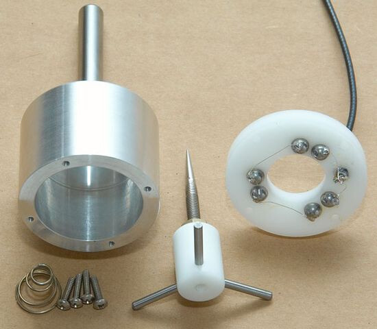
Unless that’s what you’re already doing, haven’t seen the design for it.
That’s exactly what I have been doing. But right now everything is printed, didn’t tweak all tolerances perfectly and even the printed probe tends to bend a bit.
I’ll create a separate topic for it in due time as I am progressing and have cleaned up the design a bit.
1 Like
I printed an armature around the 3D print head, attached many N52 8mmx2mm on it to lock any axis movement, printed an armature to whatever I want to attach - in this case a digital gauge (in this case I attach to the right side - in green), an done, run calibration. It’s working great.
Note if you go down this path: The way you attach the magnets, obviously, matters.
To admins (@admins), where can we get 3D models (Fusion 360 compatible, STL, whatever) of the printer components? It’s hard to “foster a community” if you don’t share that with creators.
1 Like
Nice idea, are you sharing that design somewhere?
@brvdboss Final design:
- Support magnetic (any N52 6mm diameter) attachment
- Support fixed attachment:
- Base in the top to ensure it’s aligned with the head (use a small bubble spirit level)
- Mark in the left/top to align with even more precision: cross-hair laser

Note: Print slow
3d-head-armature.zip (761.4 KB)
head-armature-att.zip (105.9 KB)
2 Likes
Thanks for sharing. Just to make sure I understand correctly:
- the 6mm diameter magnet: those are the holes on the “inside”. it might be relevant to have some kind of anti-slip thing for the attachment not to slide around.
- the way you attach your tools now is using the screws in the smaller (3mm) holes (where the heat-set inserts go). Based on your first design I assumed you were using magnets all over the design.
Would love to see a picture of it mounted.
On the magnets:
- I apply glue + press then, they stay fixed.
- They are the holes inside. They were outside, but I improved and ended up with them inside.
On how I attach any tool:
- Will depend on the tool. I now have a pen, and a soldering iron attachment too. Regarding the digital gauge, I use magnets.
1 Like
Would love to see a picture of it mounted.
First incarnation/version. Note: no movement at all.
Background on how all this started:
I have an expensive skillet that was supposed to never bulge. The brand support didn’t believe me, well, I proved them wrong, now I have a new skillet.
2 Likes