I have a failed linear module on my A350. I’m not alone. I am currently looking into repairing my module as getting another one takes an absurd amount of time. Not to mention, since I’m in the bracket of folks who, according to snapmaker, got modules that “fell below their level of quality”. So, I may not have just one poorly built rail module, but 5… That doesn’t give me a warm and fuzzy feeling.
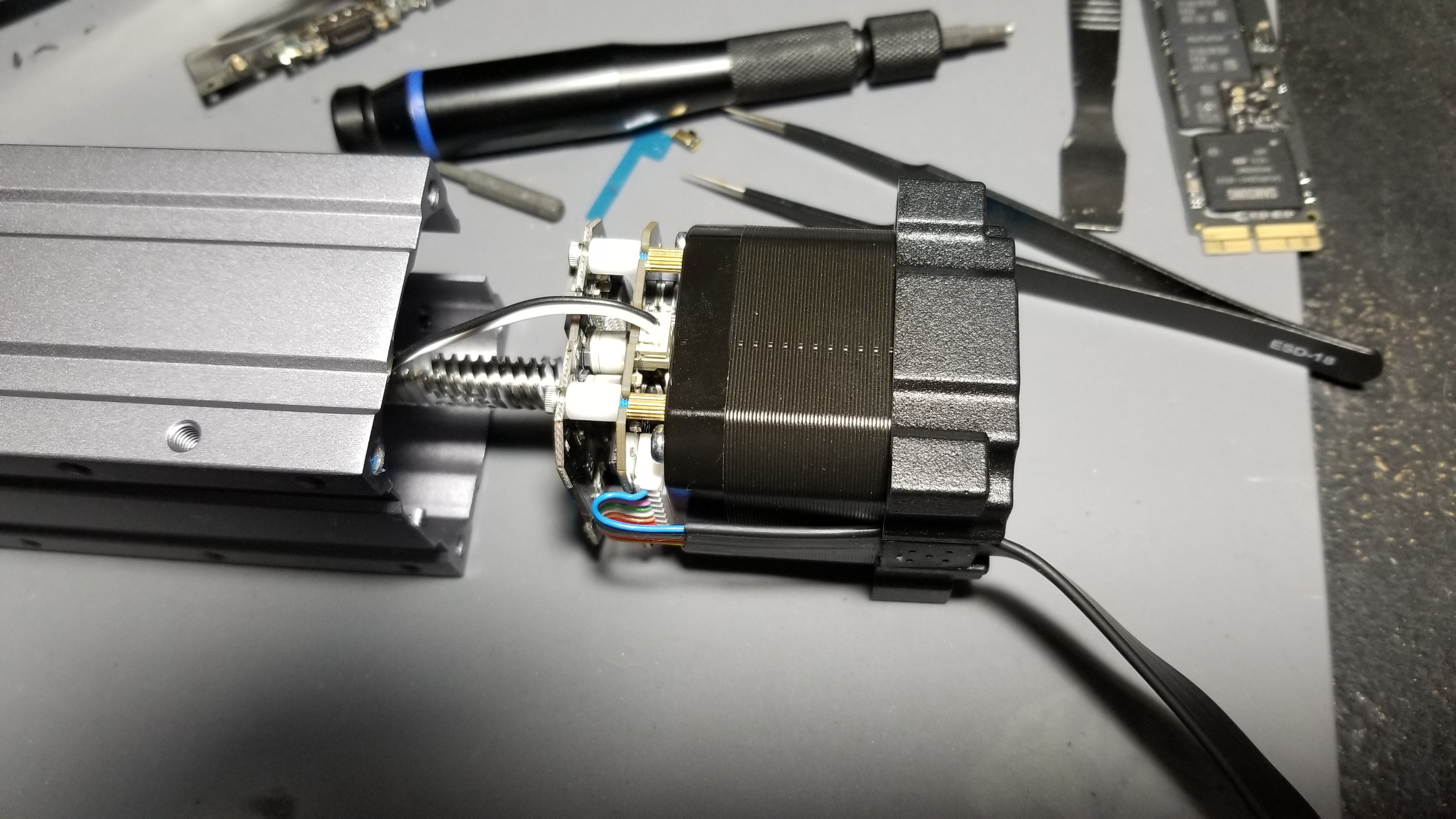
So. Being an electrical repair hobbyist (I fix iphones, macbooks and other devices), so I took a look. After all, this rail module is useless to me the way it is and there’s another on it’s way. Here’s what I found…
The breakdown is rather straight forward.
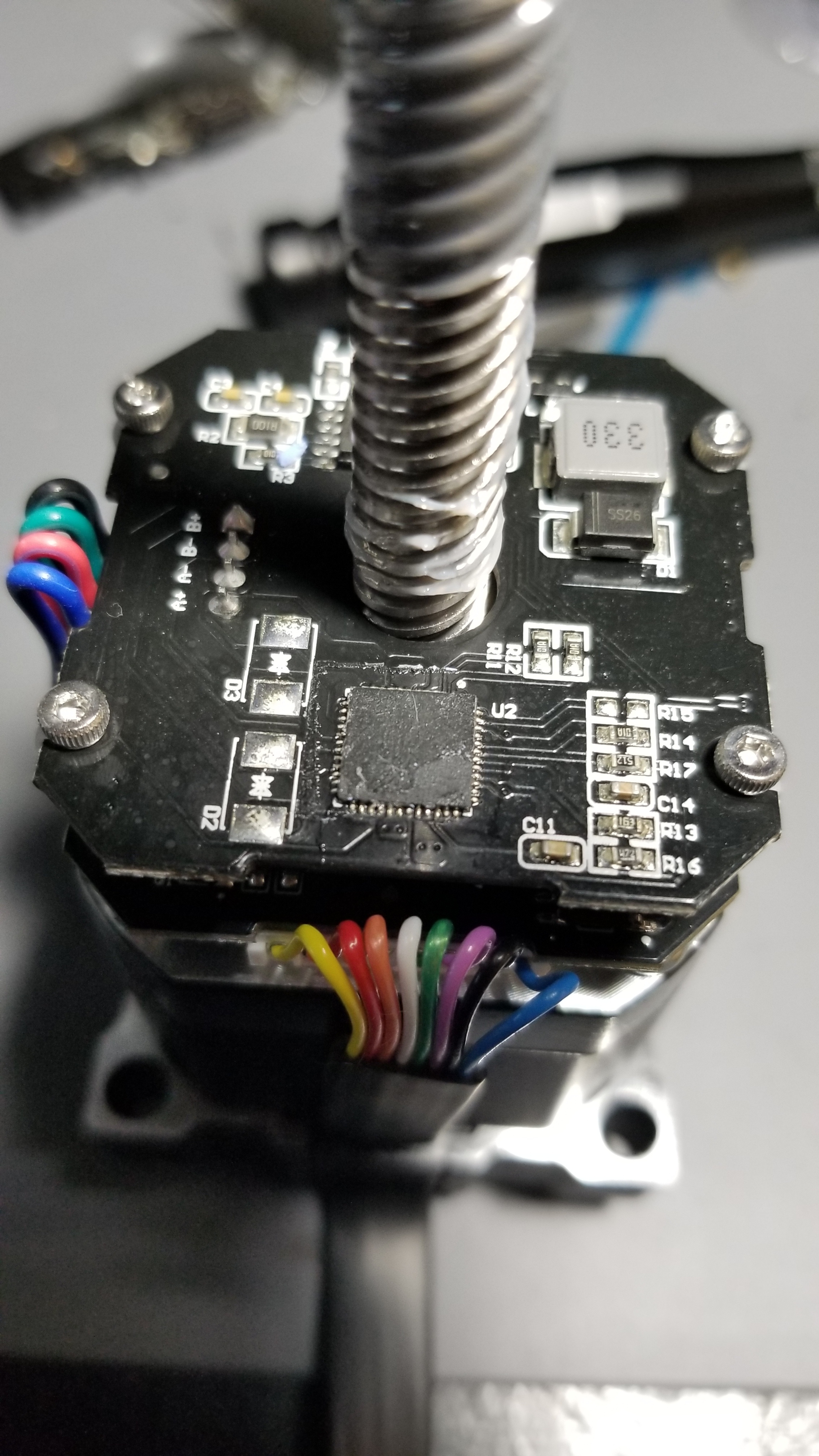
Otherwise, I found no failed solder joints, nothing apparently burnt or traces broken, although a bit more solder could have been used in some places I found no breaks. This uses the lead free solder which takes higher temps to melt.
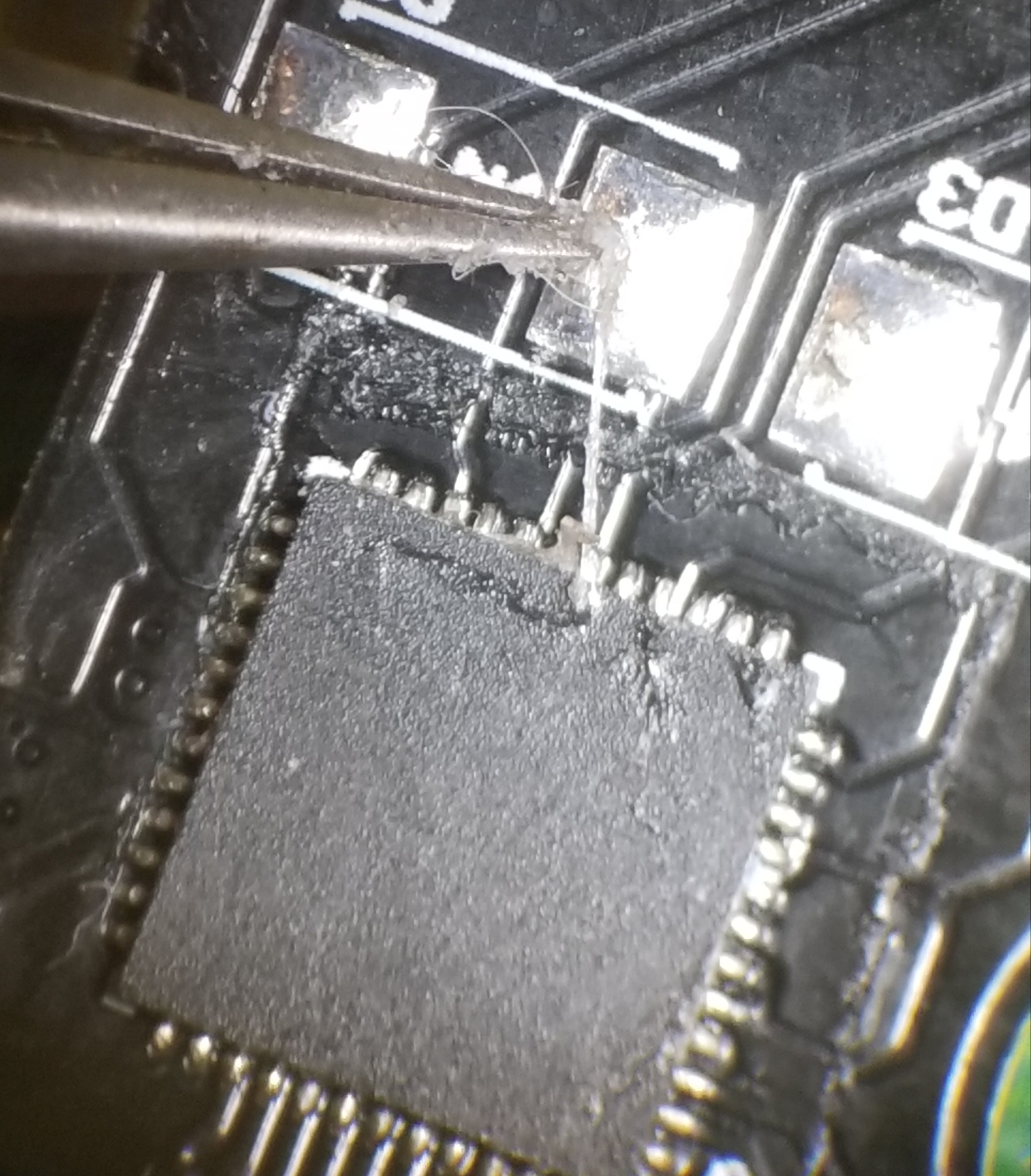
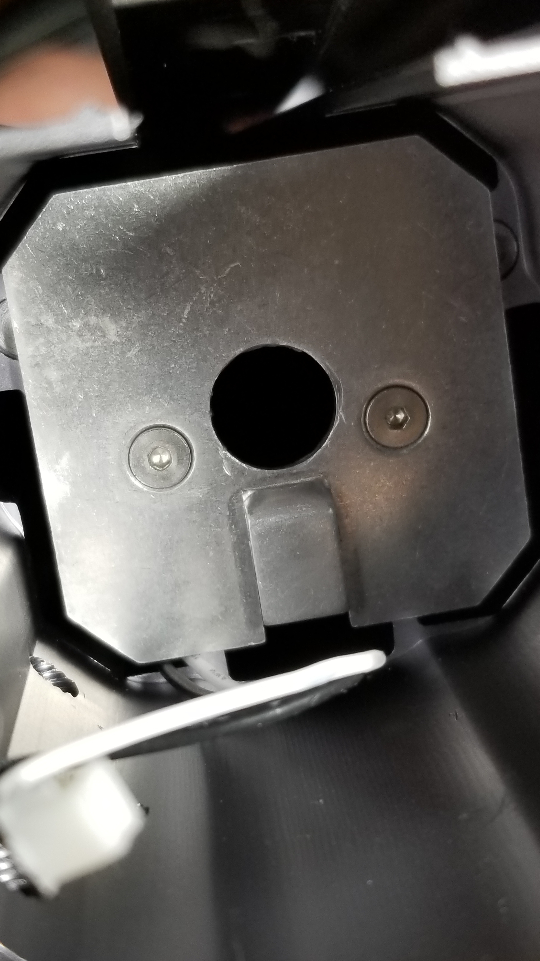
The primary suspect is this, the stepper motor driver IC. These are BiCD clock-input 2 phase bipolar stepping motor driver that use PWM current contol capable of 1/32 step resolution. Here I’m taking the booger like glue off under my microscope. I believe this is the culprit as commands are being sent, no errors are coming back, it just doesn’t move. Further testing is needed. These stepper motor drivers are temperature sensitive. This is what they put that little blue thermal pad on and uses the rail holder inside the housing as a heatsink. You can see it here.
What I found next could be an issue. They used a GD32F103 microcontroller as seen here:
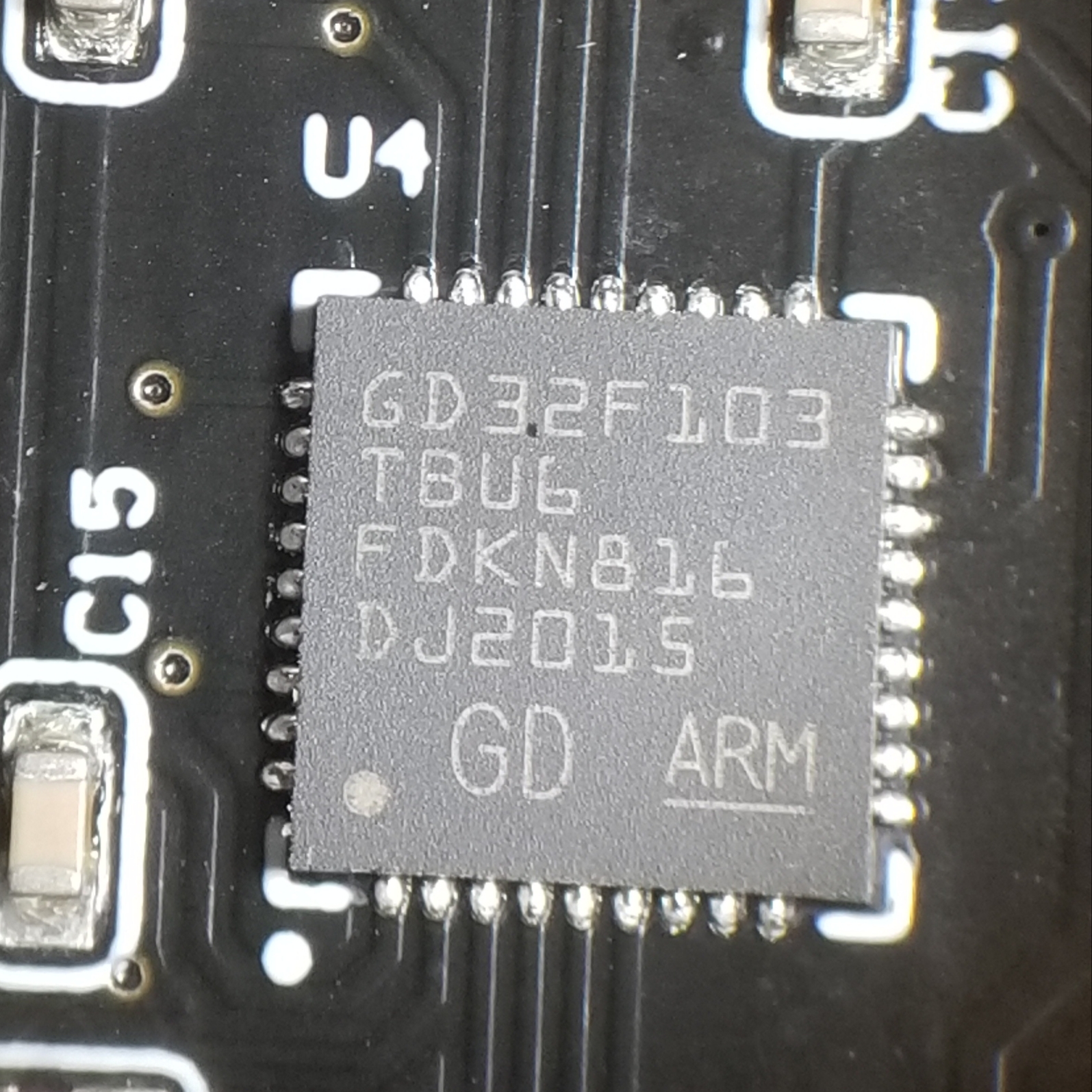
These are ARM Cortex-M3 series microcontroller clones or copies (possibly illegal copies, I don’t know, not my business) made by Giga Devices. Now why is this an issue? If this failed, sure, I can replace it, a relatively straightforward procedure with my hot air rework station. It’s not expensive either, I can get the Cortex microcontroller for under $5, the Giga Devices are even cheaper. Given the option I’d get the Cortex. The problem we run into is these microcontrollers are flash programmed. Programing them also isn’t an issue, it’s actually a relatively easy procedure that uses an inexpensive USB device. The issue is I don’t have access to the flash coding that is needed to make it do what it needs to do.
Please note this is not a fix. It’s a work in progress.

