Dialing in new fillament

I’m hoping some of you experts can help me understand what I’m doing, or at least confirm that I’m on the right track, before I spend too much time messing with settings!

I’ve nearly finished my first roll of Snapmaker filament, which I’ve been printing just fine with using standard settings, so have bought some new stuff, but another brand (Tucab Fil3D PLA), so figured it was time to up my game a little and try and make sure I’m printing the best I can. Also, the first thing I tried with it came out horrible, because I hadn’t realised that a firmware update had reset the extruder setting!

So, please bear with me, this might drag on a bit, as I’d like to just explain where I’m at and see if anyone has any ideas on what I should do differently.

First off, I’ve calibrated the extruder, and got that to near enough bang on 100mm.

Then, I printed a temperature tower, which came out like this:


I didn’t really see much difference between the temperatures initially, so stuck with 210º (the spec sheet recommends 210º ± 20º). But, then I noticed that it gets a lot glossier the hotter it was, and that down at 190º it is more semi matt, like the original Snapmaker filament was.

This is a sample of both filaments, and the tower against the roll:


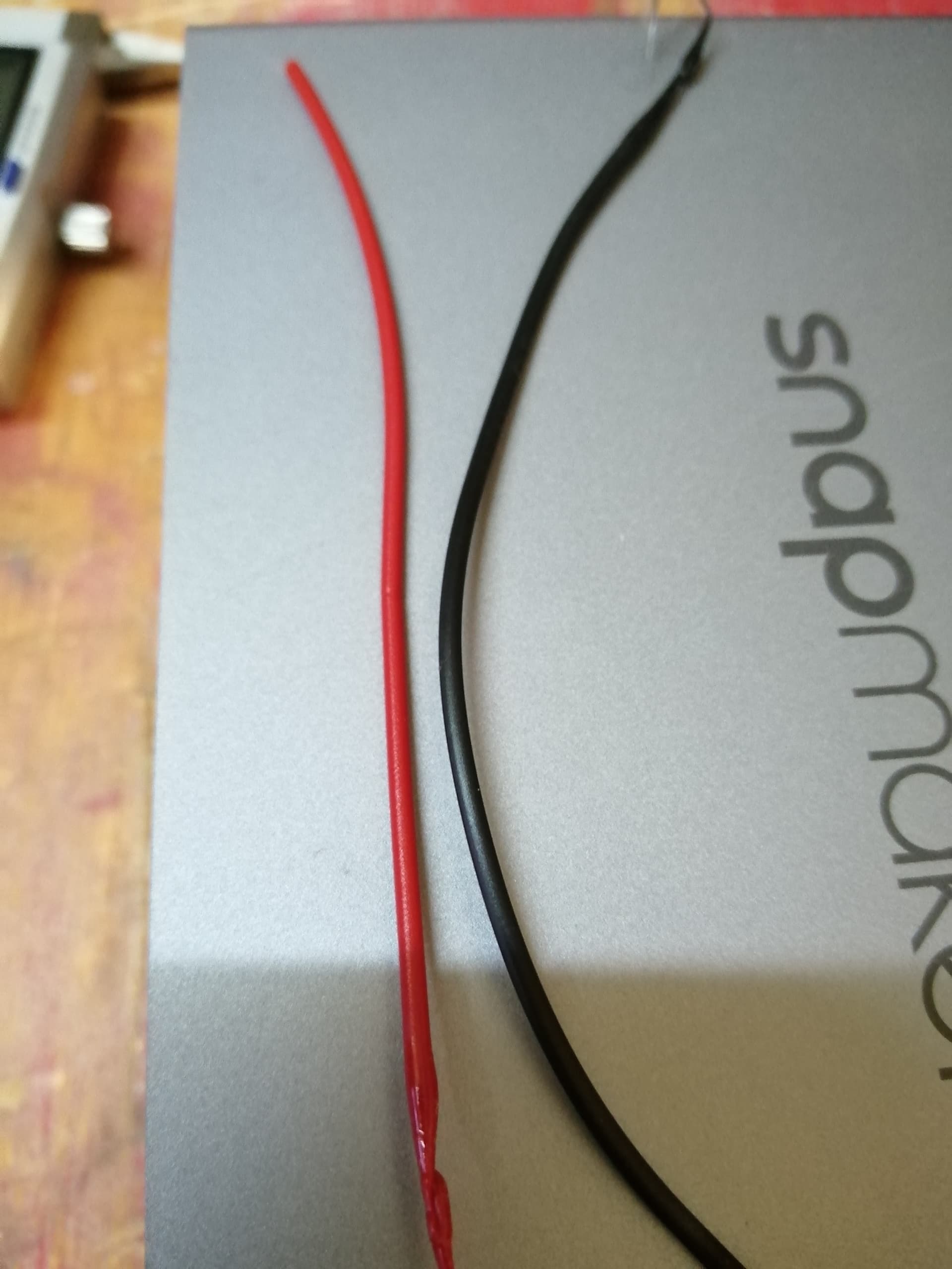
So, I’m now thinking I should only be printing at 190º. Would that be right?

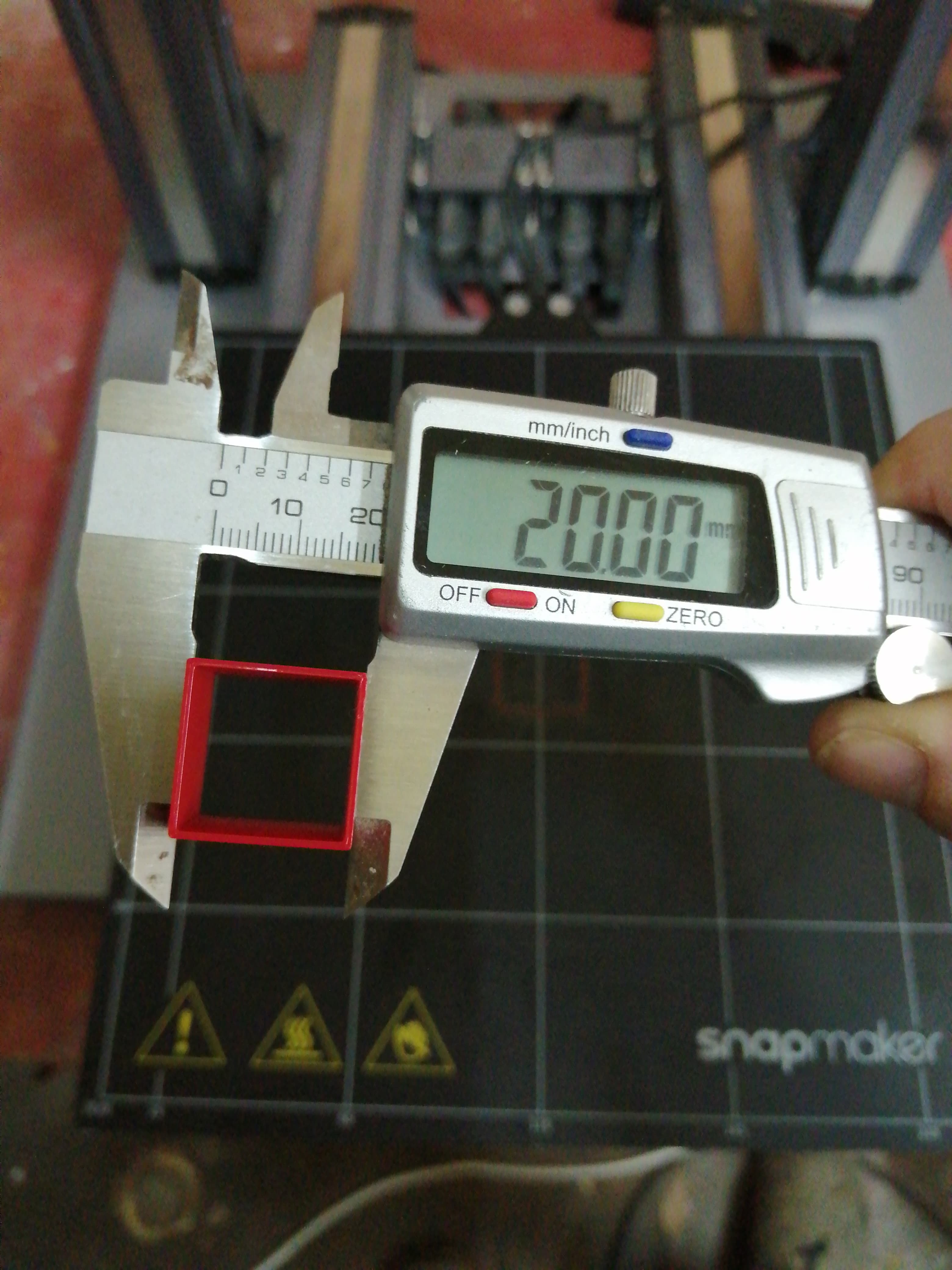
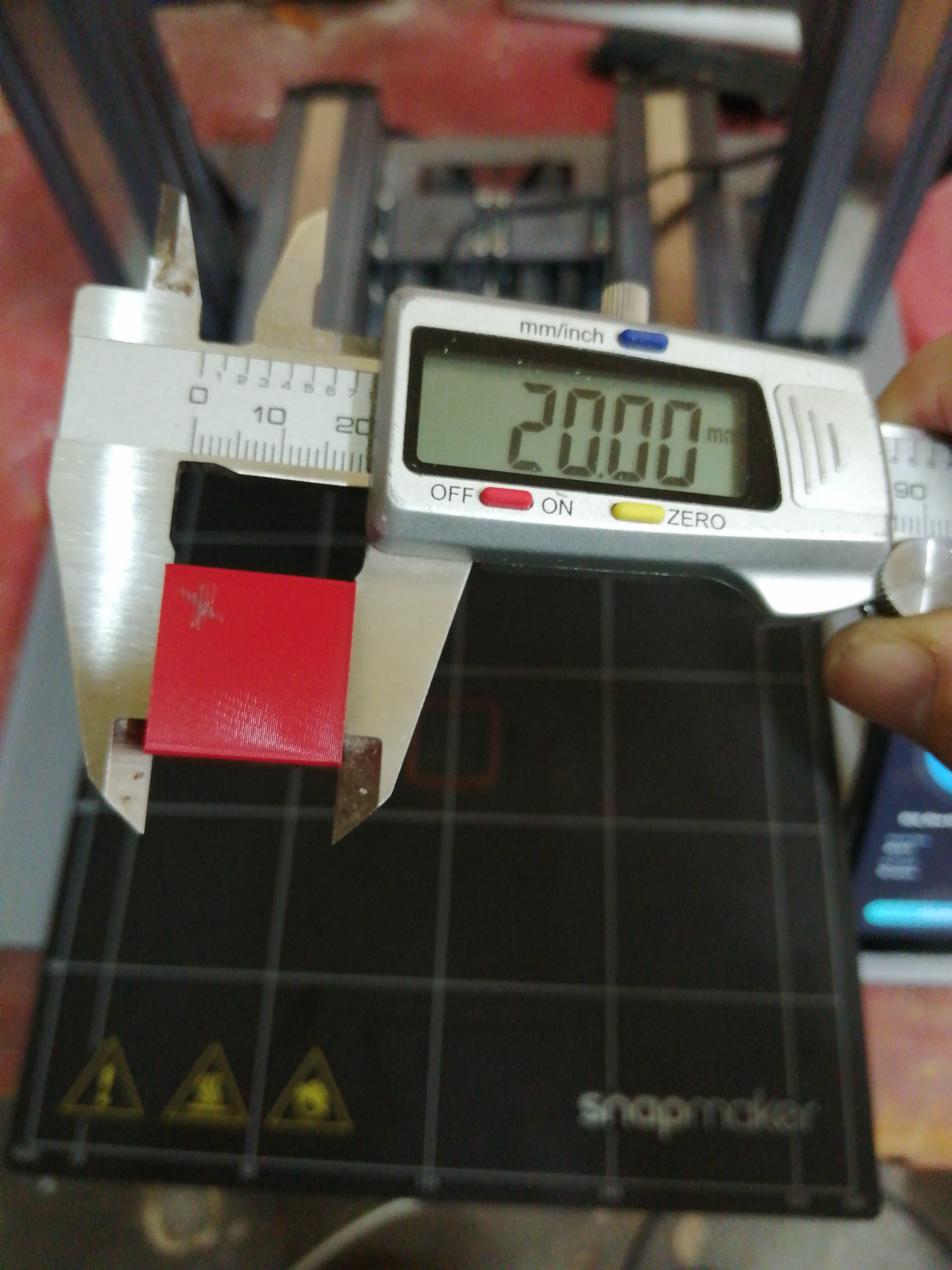
Then, I moved onto printing a small flow test cube to check the wall thickness. This was 2 walls at 0.4mm each, and at 100% flow the walls were coming out around 0.95mm (instead of 0.8mm). A couple of different rates were tried and at 90% flow rate, I got pretty damn close:


OK, actually, perfect! But, that was at 210º, so I guess if I do switch down to 190º then I should recheck this as I guess the flow rate will be different at a different temperature?

Next question is, is it normal for the first layer to be much wider? I always seem to get quite a noticeable lip on the bottom of a print, as you can see by the thickness of the bottom of the above cube:


It’s nearly twice the thickness of the rest of the print. Is that normal, or should I look at changing some first layer settings?

On the subject of first layers, a few bigger parts I’ve tried with this new filament seemed to be quite nasty on the first layer. Admittedly, this one was done at a guess of the flow rate at 85% before I rechecked it, but the skirt was almost non-existent in places and the actual part, well, you can see how uneven it is:


Could this have been because of the slightly underrated flow (not a massive difference, I wouldn’t have thought), or could it be because it was too hot? Or is there something else going on there?
The second layer seemed to be a lot better, and the finished print looked ok, although was a bit “holey” on the bottom:

All of the above was done with 55º bed temp. I haven’t started messing with that yet, because as far as I can tell, the prints are sticking just fine. I get the feeling it’s more about the flow and extruder temps. But maybe I’m wrong?

Final question for now - because of these very fine skirt lines, I have a lot of very thin residue on the print bed (which actually look thicker/more obvious in the photo than they actually do). Too thin to get the spatula under it, or scrape it, but too thick to be cleaned off with alcohol:


It goes against the concept of the sheet, but as new there is a kind of non-stick type texture to the sheet, which I’m worried about damaging by scraping too hard. You can see some spots are already turning shiny. Any ideas for cleaning these off? Or am I worrying about nothing, and it’s OK to just scrape away at it?

If you’re still with me, thanks in advance for any tips you can offer!

You’ll likely always have a little bit of this, yes—it’s called “elephant’s foot”. There are mitigation strategies you can use, like tweaking the “initial layer line width” setting in Luban.

That looks like it could be a leveling issue—if the nozzle is too close to the build surface, the plastic can’t come out (or if it’s too far away, it won’t stick, obviously). Try tweaking the nozzle up or down in very small increments, and if you did the standard 5x5 autolevel, you might want to retry with an 11x11 or something. (It could also be underextrusion, or something else I haven’t thought of.)

you might want to retry with an 11x11 or something.

I’ve done the auto level from the touchscreen. How do you go about doing something different?

As far as I know, to do an 11x11, you’ll need to attach a computer to the USB-mini-B port on the Snapmaker controller and run the gcode directly. The last post in Calibration madness - #9 by scyto lists the gcode to run. (Also, the autolevel is 3x3, not 5x5. I guess I haven’t done it in so long that I forgot.)

Ok, thanks. I’ll try some more tests with different temps and flow rates first then, as I have a slight problem in that my computer and printer live 20 km away from each other, and I’ve only just taken it back home after redoing the extruder calibration!

I agree with ElloryJaye. The elephants foot, the non-existent skirt, and the rough texture of the first layer looks like your print head is too close. Which makes the skirt more difficult to get off because it’s thinner than paper at that point.

I’ve had good luck getting stuck on filament off by fixing the calibration, then overprinting a waste piece. I have a 120mm x 120mm x 0.05mm object I use to calibrate my original, and it does a good job of getting stuck filament off the bed (or becoming stuck on filament when the calibration is off). I have destroyed a bed sticker trying to get those off with a pallet knife. I even damaged the heated bed, and had to file down some rough edges around the gouges. It still works, but I bought a replacement in case it didn’t.

Being able to change the finish of your part from matte to semi-gloss is kind of cool. That can be handy depending on what you want the finish to look like.

I’ve run another, lower temperature tower, and I think that confirms my suspicion about it being too hot. This time there is a clearer difference (it wouldn’t even print the last 170° section) where there is a range around 185-190 that comes out matt. Weirdly it starts going glossy again when it gets cooler too?!

I’m just testing some more of the little flow cubes as well, but I’m not sure about the nozzle height. I tried raising it just 0.05mm from where I think it should be using the card and the first layer wouldn’t stick at all.

I redid the auto level to where I normaly would and it was better, but actually the first layer still wasn’t sticking at 190.

I managed to get a good result by leaving the first layer at 210, and with 95% flow, and it’s got much less of the elephants foot. I’ll have to wait till tomorrow to try a bigger part again.

But now something else has cropped up. On every one of the little cubes I’ve done, the right side wall (closest to the touch screen) has printed the two walls right together which with the new settings measure near enough 0.8mm. The other three walls have a visible gap between them. I can squeeze them together with the calipers and they still measure near enough the same, but why would this one side always print differently?

… I’m confused too. That looks like left, upper, and lower walls are thicker than the right wall. Like an inner and outer shell were deliberately created. You said the gapped walls measure 0.8mm when you squish them together? What do they measure when you don’t force the gap closed? Does the original print have differing thicknesses like that too?

It’s a bit hard to measure them accurately without squashing them, but if say they are close to 1mm.

By original print, do you mean the model dimensions on the computer, or the first one I printed at full flow rate?

The full flow rate one is the same, just less noticeable with the thicker walls. I’ll double check the model when I get back to the computer later, but it was just one I got from thingiverse and put straight into cura.

The outer dimensions are slightly different to, presumably because of this. There’s some sort of xyz calibration you do as well isn’t there? Maybe I should do that too?

OK, I’ve just checked the model file. In Fusion, it’s hard to tell exactly, as for some reason it open it 10x the size it actually is. So, I’ve drawn up my own version, making sure the walls are 0.8mm thick and the outer dimensions are all 20mm.
Comparing the previews in Cura, you can definitely see a difference, so maybe the original model file I had wasn’t quite right. I did notice the gap before in this preview, but just assumed it was how cura was showing the lines. But you can see the new model, the walls are much closer together.

This was the original file:

And this is my new file:

So, I’ll try reprinting some of these new ones next and see how they come out.

Well, I guess this proves you can’t trust anything you find online!
First print of my own cube came out near perfect. There’s still a small difference between the x and y outer dimensions (it’s a bit short across the x face) , but the four walls are much closer.

Only slightly odd thing now is that the front x wall is a few hundredths thicker than the other three!


You’re always going to have some variation. It’s hard to even measure a plastic piece that accurately.
Do you have an enclosure? It doesn’t look like you do. If it’s near a window or air vent you may end up with variations just from that.

-S

The true test is what happens when you double the X, Y, and Z dimensions. What is the variance then? I’ve seen people dial in a 20.00mm cube to perfection, but when they print anything else, the dimensions are all out of wack. +/- 0.10mm is normal for any print, at any size, and most designers usually account for a +/- 0.20mm variance in their designs.

1 Like

Yes, I think I’m going to call it good enough. I printed a 40mm disc part that I have, and that came out pretty much right.

OK, so turns out you may have been right. After all the testing, things seemed to be going well until I tried a bigger part again (well, 2 separate parts, but covering a larger footprint). The first part, in the centre of the bed, was looking lovely, but then the second one, further out, started getting a bit rough again. As you can see:

But, after a little playing around with the touchscreen, I’ve found that you can now change the settings for the auto-level. Under the settings menu, then 3D printing, you can now select a 3x3, 4x4 or 5x5 grid (this is for the A250), and you can turn the heated bed on for calibrating. So, after doing a 5x5 calibration, it now seems to be a lot better:

I’ve also started using 3 skirt lines, as it makes it much easier to remove, as yes, the bed is starting to clean up as I go over the stuck bits.

3x3. 4x4. and 5x5 have always been available, you just need to change it from the default 3x3. Over USB, you can go up to 11x11, which is what I use. There are several posts on 11x11 calibration.