I am a proficient machinist and really want to leverage my A350 as much as I can including complex machining of non ferrous materials.
Perhaps we can get a thinktank going?
CAD/CAM - seems Fusion 360 for post processing is the only real option at the moment?
Notepad for editing in custom moves? eg. tool change
A long time ago in a galaxy far far away we wrote code in Excel and machined million dollar parts…
Tooling management - Interesting one, I will be doing a lot of tool changes…
I’ve often used an alternative origin point we called ‘the button’ (hardened steel calibration point on the bed) Repeatability and accuracy between tool changes and repositioning of the workpiece is the key here.
Stock management - As above, I have used many methods including sacrificial boards. Should not be to hard to refine this.
Waste/Swarf management - Seems to be some vac heads available to print but swarf evacuation is an issue and metals such as aluminium really require some assistance with cutting fluid…
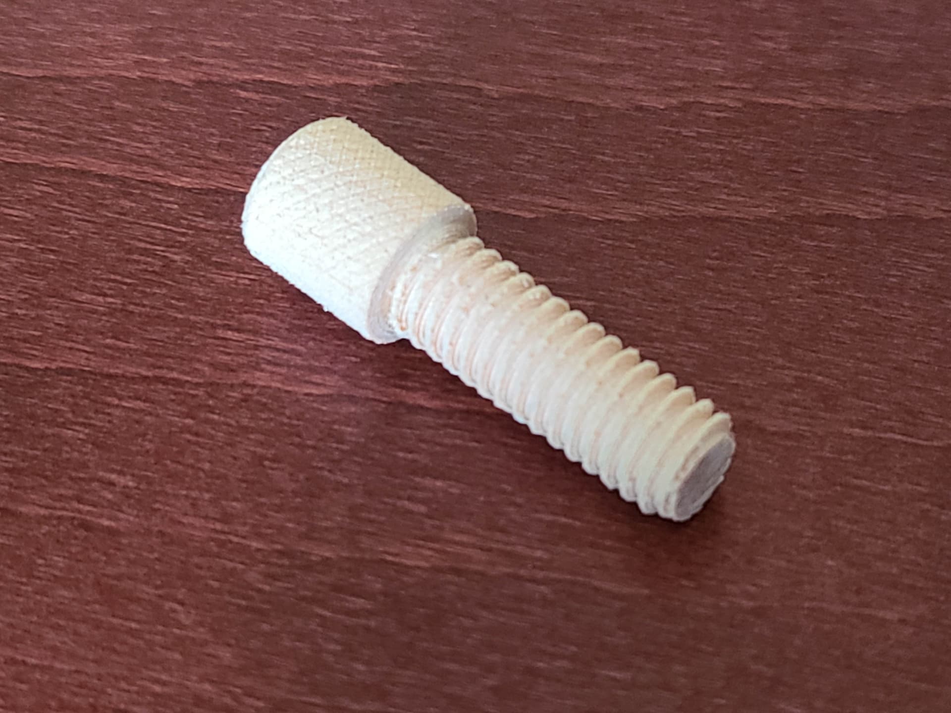
Thread Milling & Other musings…
90 degree head and 4th axis thread cutting/milling would be cool! hmmm
I’m sure I’ve not found every barrier with this platform yet so chime in and I’ll update the list.
You’re ignoring the two most glaring barriers to using this platform for metals:
Power and rigidity. It simply isn’t powerful enough or sturdy enough to mill metal.
And those who’ve been able to get it to have to go ridiculously slow.
Most of this stuff has been covered if you search.
Nothing is stopping you from writing your gcode manually. Fusion is the most easily accessible tool right now. estlcam, freecad, kiri:moto, meshcam and others can be used as well, although some might not be 100% compatible with the SM or the type of work you want to do
You can still do that. I’ve already done it myself and just connect it with a multimeter on the resistance setting and adjusting manually till it beeps. I’ve thought on automating it with some custom gcode, but never got round to it. In most cases, adapting the origin to be the same for all operations is easier and then you only need to worry about the z-height. Just make sure you have a point where it doesn’t get machined away. Much easier
Aluminium should be possible without real cooling (just aircooling by the toolhead), definitely taking into account possible workspeeds and depth of cut with the SM2. Any type of fluid cooling will be a problem anyway. The design didn’t even try to make it waterproof o forget about that. You’ve bought the wrong machine
You bought the wrong machine
The biggest problem right now are your expectations. You’ve bought the wrong machine for your wish list
Then you should be aware of the limitations of the machine.
It’s fun to dream, but I honestly think you should manage your expectations. You can do a lot with the SM2, but it won’t be fast and it has it’s limitations with regard to materials that you can use. Stay within those boundaries and it’s a great device. Stretch them too much and you’ll be disappointed.
@pugs the conclusion is still the same, the Snapmaker was not designed to mill metal, it does not have a spindle powerful to do so nor is the machines design rigid enough to handle it. I’ve done a very small amount of aluminum milling on it, the spindle doesn’t keep parallel as it is not designed to handle the force necessary to handle milling metals. It does it OK if you use extremely small step downs but it defeats the purpose as it turns a simple job into a very long one. It’s not practical, especially if you want to do it at normal speeds like other machines that can handle metal milling.
Pugs what did you come up with for your minimum feeds and speeds for the cutters you’re using for the material? Any time I’ve done that in results in a spindle wattage requirement far above the 50W available for anything in the ballpark of traditionally acceptable.
It’s not impossible to mill non ferrous but it requires creativity.
What if the minimum is simply “not having to do it with my power tools in a jig”?
I see everyone here saying that the speed/power is just unacceptable, bit if I’m wiling to go at FDM or slower speeds (.02 mm cuts at ~40mm/s, maybe a 2mm diameter bit), will the machine be able to “mill” some aluminum? (I’ve never done any cnc, but I was hoping to mill out a bottle opener belt clip for my knife maybe). Yes it’ll take hours for a simple cut, but it won’t be as janky as if I tried to use my jigsaw (and even then, maybe I use my jigsaw for some clearing cuts, and just finish with the machine).
It can be done but you should be aware of how chip load affects they process.
To make it work with the available power you run at slow speeds. What ends up happening is the cutter stops making well formed chips and ends up doing something more akin to grinding through the material.
This leads to increased heating in the cutter and a shorter life than it should have.
Spoken like a true Machinist. I’m up for a challenge Pugs. Been a CNC machinist for 30some years myself. I’ve got access to Solidworks and OneCNC. I’ve modded my Snapmaker with a couple of linear rails to support the bed I think this is a necessity to even try and do some (semi) serious CNC work.
And thread milling in non metal material will be possible with the right toolheads. Estlcam has some nice features to make that possible : https://youtu.be/xO-GHEIIOQQ
And if you do a search on the forum and on YouTube, there are people who have already done some work on aluminium.
Overall, the results aren’t great and it will definitely impact the lifetime of your device.
But feel free to try and show us how it’s done.
But don’t say we didn’t warn you
Clearly the issue here is rigidity. You basically have none. Threadmilling a small hole in 6061 should be do-able, but not optimal. 8-32 - 1/4-20 should be possible. Threadmilliing is usually done in six or seven or more passes, with little radial chip load anyway. Adaptive milling, or far worse, slotting is going to be loud, frustrating and get expensive.
Tooling management - Interesting one, I will be doing a lot of tool changes…
I actually came here to look at the horizontal expansion (holes are more like ovals in the prints) fixes and saw this topic. I started to do the topology maps (small- ~ 160mm x) and need to change the bits frequently so I made a set of 3d printed bit setters at different lengths that help with keeping the same Z setting between bit changes. It indexes off of the bottom of the collet and has a small platform for the bit tip (also helping with holding the bit at length while you tighten the collet) and it results in being very close to the original Z. Not 100%, but maybe a few thousands off as printed. Smoothing out the lines/valleys in the platform would certainly increase accuracy. It works well and reduces the need to do math between the new z and old z and offset of the previous work z to continue the milling.
I’ve played with the feeds and speeds, used GWizard, tried the couple suggestions for bit depths max cuts, step overs and completed a few projects in softwoods as tests. The unit deflects quite a bit when it encounters harder areas (on the late season grain rings) and jerks/ chatters a lot on climbing passes regardless of step over/ chipload settings. It would be needing well above 20+ hours of milling time on the setting where it doesn’t deflect and that is just not an economical solution. Knowing that the other two modules share the linear rail, I upgraded to a shapeoko for cnc’ing. I’ll use the SM for surface work like engraving the details on the back and for the rotary if I need to engrave pens, but gotta use the right tool for the job.


 Spoken like a true Machinist. I’m up for a challenge Pugs. Been a CNC machinist for 30some years myself. I’ve got access to Solidworks and OneCNC. I’ve modded my Snapmaker with a couple of linear rails to support the bed I think this is a necessity to even try and do some (semi) serious CNC work.