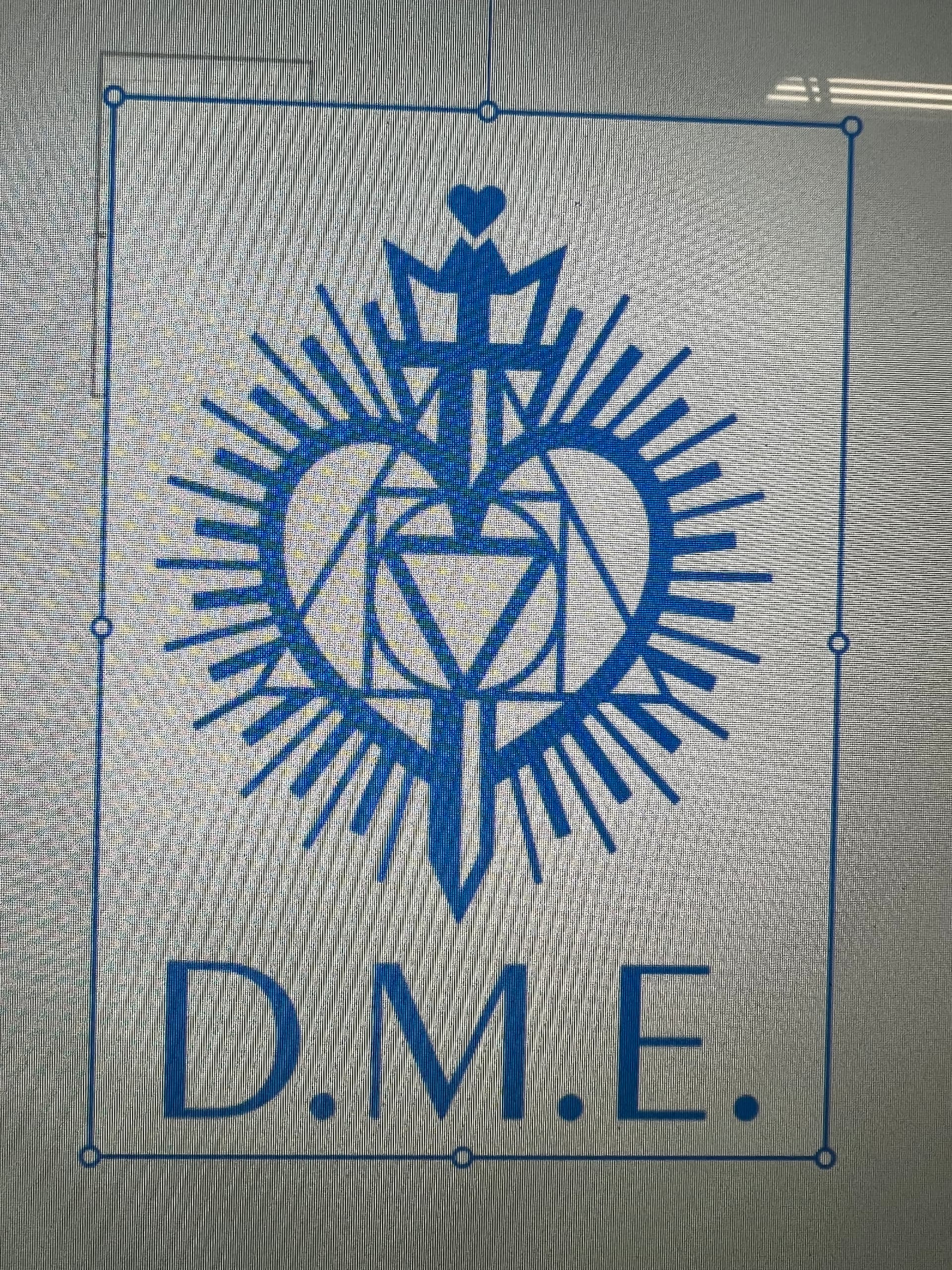
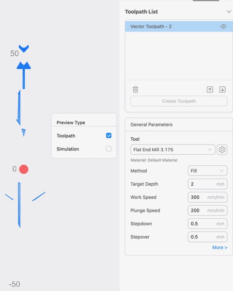
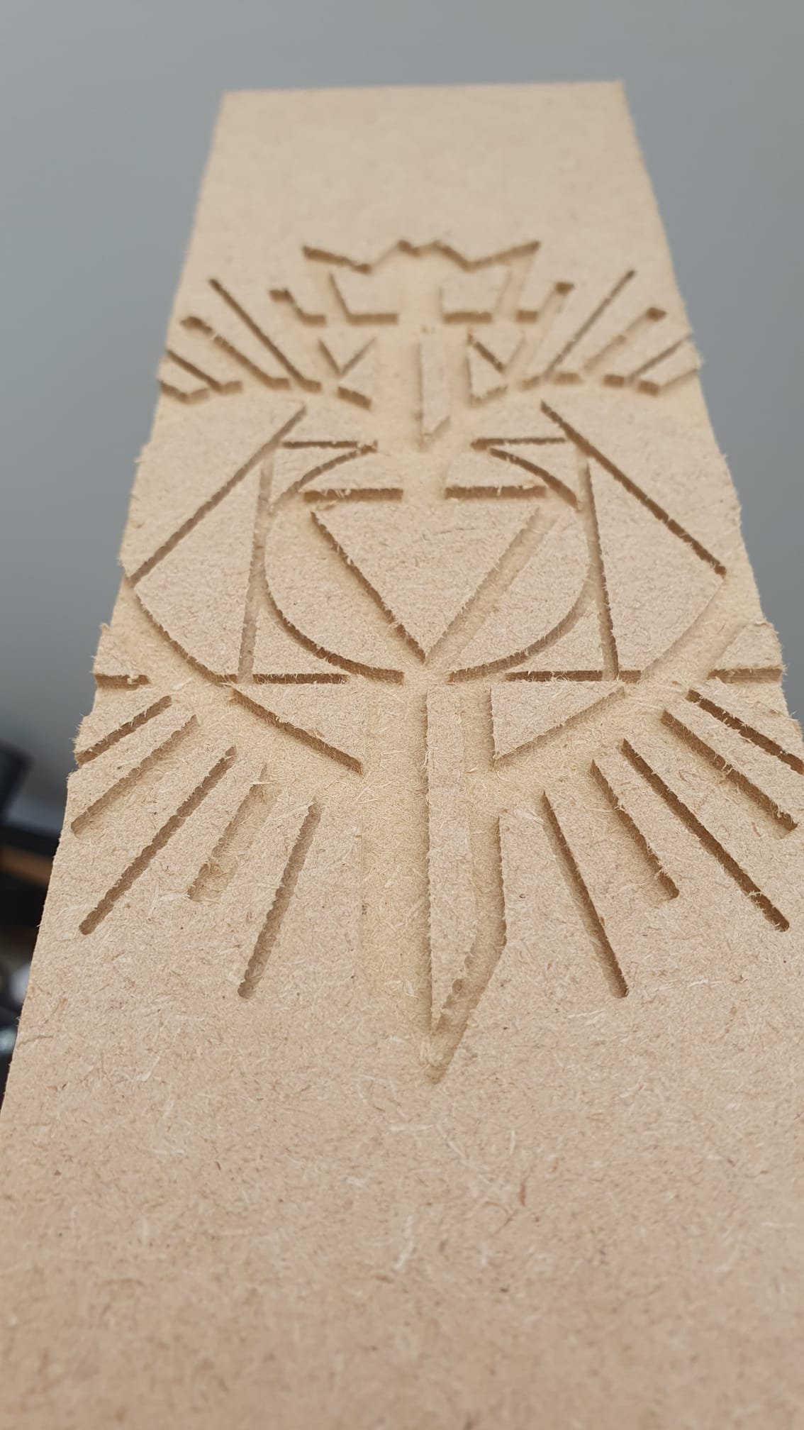
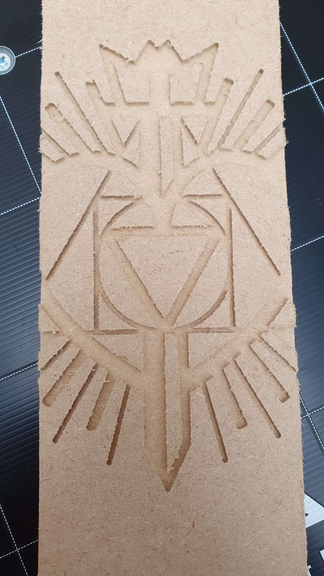
Why doesn’t this file convert correctly to a tool path? I tried cutting in vector but it left some areas uncut as in the third photo. The first photo is what it looks like on Luban before I generate code. The second photo is what it looks like after it converts

You have ‘Cutting on the path’ selected. This is part of the Vector profile, which is incorrect for your image.
I am not even sure Luban can do this. You may have reached the limits of what Luban can do on the CNC side. Someone who has more experience may be able to help.
It looks like your toolpath has followed the periphery of all your black areas. Luban is pretty basic in that you can only choose On the Path or Outline (what ever that means) or fill (with a zig-zag pattern that doesn’t even follow pseudo paths, that doesn’t take much thought!), not even ‘inside the path’. I once had to do a fill first and then a separate toolpath as an outline to clean up the remains of the zig-zag rough edges.
Are all your image lines wider than your tool diameter?
I can give it a go if you are willing to share the image?
Last time I tried Luban for CNC it only has “on path”, not “inside path” or “outside path”which is huge shortcoming. Now I just use illustrator to make my own CNC paths.
Good morning,
Yes the image lines are larger than the tool diameter. Here is the file if you would like to try. So what you’re saying is Luban doesn’t have the capability to design the cut but can cut it if it is designed properly?
Thank you for any help you may be able to supply,
Debra

Thank you1
As I thought, it’s almost certain that the tool diameter you have used in your toolpath is too large for most of the elements of the image. That is why much of it is disappearing in the preview.
You said you want to cut the image at a total width of 3". I have tried it at 5" wide and found that a cutter of 3.175 causes various areas to not be processed. I have done it with a 1.5mm cutter with success for a 5" image.
But, shrinking the image down to 3" wide causes much of the tool-paths to go missing. In fact only a tool diameter of 0.9mm or less will work when the image is 3" wide.
Several points:
- When you choose the Vector ‘Processing Mode’ you then need to choose the ‘Fill’ Method. It’s a very inefficient tool-path, all the zig-zagging, but at least this mode also creates a tool-path that runs around inside the boundaries therefore cleaning up all the mess from the zig-zagging. I don’t know why they couldn’t create a mode to produce this ‘inside path’ tool-path separately.
Ideally, even with ‘Fill’, I’d prefer to see a more efficient tool-path method that always runs parallel to the boundaries instead of all spot cuts and zig-zagging. I will experiment with Fusion 360. - To be continued…
Oh I am sorry this is such a hassel. I did use the fill method and it was the same. Do you think I can use a .9 tool diameter and can I even find one that size?
No hassle, it forces me to go and learn a bit more. ![]()
There are plenty of 0.9mm on Amazon in the UK, not sure where you are.
I scaled the image down by typing 76mm in Luban for the width of the image, if you do something slightly different you may get away with 1.0mm or be forced to use 0.8mm - when you generate the preview look for the thinner lines disappearing.
That’s amazing. I will look for a proper size bit and see if that works. I get the part about learning but I am 70 and sometimes don’t look at things differently and figure it out. I really appreciate your guidance. I live in California USA.
Enjoy your day,
Debra