- Generate Laser file for the rotary module. (SVG, DXF, and IMG are supported)
- Generate CNC file for the rotary module. (SVG, DXF, IMG are supported)
- STL file is supported
- Rotation (For simple models without hollowing)
- Linakge (Suitable for complex, hollow models)
- STL file is supported
Laser sector workfolw
- Switch to Laser 4-axis
- Input the size, length and the diameter of the material.
- Import the file, Choolse a processing mode, Adjust the size and position
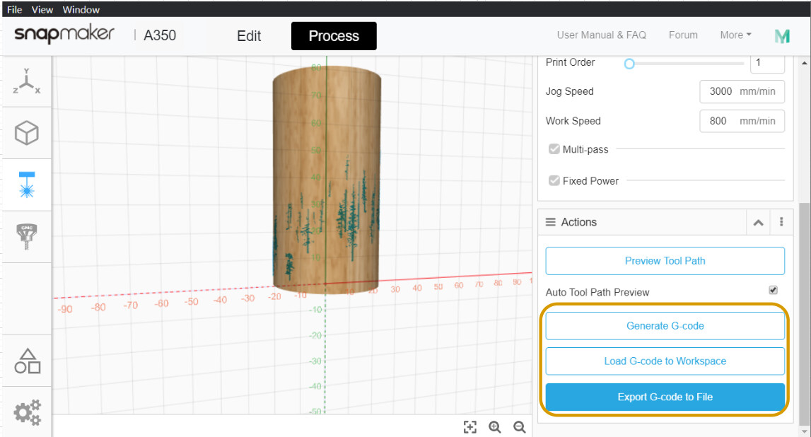
- Adjust the toolpath and preview it
- Generate G-code file and export it to USB stick or send to the machine via -Fi.


CNC section workflow
-
STEP 1 Switch to CNC 4-axis
-
STEP 2 Import the file and adjust the size, choose the position of the model.
- Placement Face
- Select the chucking surface that will align one of the model’s faces


- Image Density(Adjust the sharpness of the preview image)

Image Density = 1

Image Density = 5
- Image Density(Adjust the sharpness of the preview image)
-
STEP 3 Select the CNC bit and adjust the toolpath parameter.
- Slice Mode

- Rotation, the right one(For simple models without hollowing)
- Linakge, the left one (Suitable for complex, hollow models)
- Step Down
- The depth of each carving step
- Slice Mode
-
STEP 4 Generate the toolpath and preview it
-
STEP 5 Generate and export G-code file
-
Generate Laser file for the rotary module. (SVG, DXF, and IMG are supported)

-
Generate CNC file for the rotary module. (SVG, DXF, IMG are supported)
- STL file is supported
- Rotation (For simple models without hollowing)
- Linakge (Suitable for complex, hollow models)
- STL file is supported


