New Aluminium Bed for SM1 (CNC project)

As previously mentioned, I am going to be making a new bed for my SM1. I found the clamping system a little restricting in that there appeared to be insufficient holes to attach the clamps and this was limiting when odd shaped items had to be machined. The clamps themselves were quite soft and distorted easily with moderate pressures.

My starting point was selecting the correct size of Aluminium and understanding the durability of the product and how easy it would be to machine with mainly hand tools. I selected a T6 aluminium of grade 6061. This is a 4mm thick precipitation hardened material (to mimic the exact thickness of the current bed) that is about 97% aluminium and which is alloyed with approximately 1% magnesium and .5% silicon. It is an artificially aged version of aluminium. Its property characteristics include the highest tensile strength of all 6061 types of aluminium. This version also has good machinability and good resistance to bending and corrosion.

I only have a small area in which to work so most of my tools are hand tools. I started out by cutting a roughly sized square of aluminium from a sheet of the material, using a hacksaw and some cutting fluid to improve the smoothness of the cutting process. I then had to file the metal square and smooth the rough edges. Once the piece had been squared and smoothed, I worked on removing much of the scratched surface with wet and dry silicon paper which I graded down to 3000 grit. This has left me with a very smooth table without burrs which always have the potential for causing injury to hands.

The images below provide some sense of how the process was effected. This first image shows the sheet of aluminium clamped to the bench and the square missing. I use the cutting oil CT-90 for all of my metal against metal work and can recommend it very highly.

The next image shows the two pieces of metal together for comparison purposes. The drilled one is the standard bed supplied with Snapmaker SM1. And the final image in this series shows the relative thickness of each piece of metal.

I am getting my pillar drill back tomorrow. My original drill press (digital and very effective when it was working) broke after a very short life of about 4 weeks and the supplier could not replace it. I have ordered a new drill press which is not very sophisticated but I find having the ability to drill truly vertical holes is really crucial.

Onwards!
I want to make a particular pattern of holes in the new bed. Ideally, it would achieved by using Luban but I have a couple of issues. The CNC part of the application is not as clear to use as I would like. Having worked out where I want my 3.3mm holes (the size needed for an M4 tap) I set up a Luban drawing with 0.1mm points. I only need to mark the metal so I can drill it using my pillar drill and a cobalt drill. Then I would tap the holes by hand and use the cutting fluid shown earlier.

Luban permits me to make the points as 0.1mm but does not show them. A check using CAMotics shows that the points are not doing much in terms of creating a toolpath that would allow the Snapmaker machine to effectively centre punch my holes using a V carving bit. Have I found the limit of Luban or the Snapmaker machine?

The next illustration shows what I am trying to achieve.

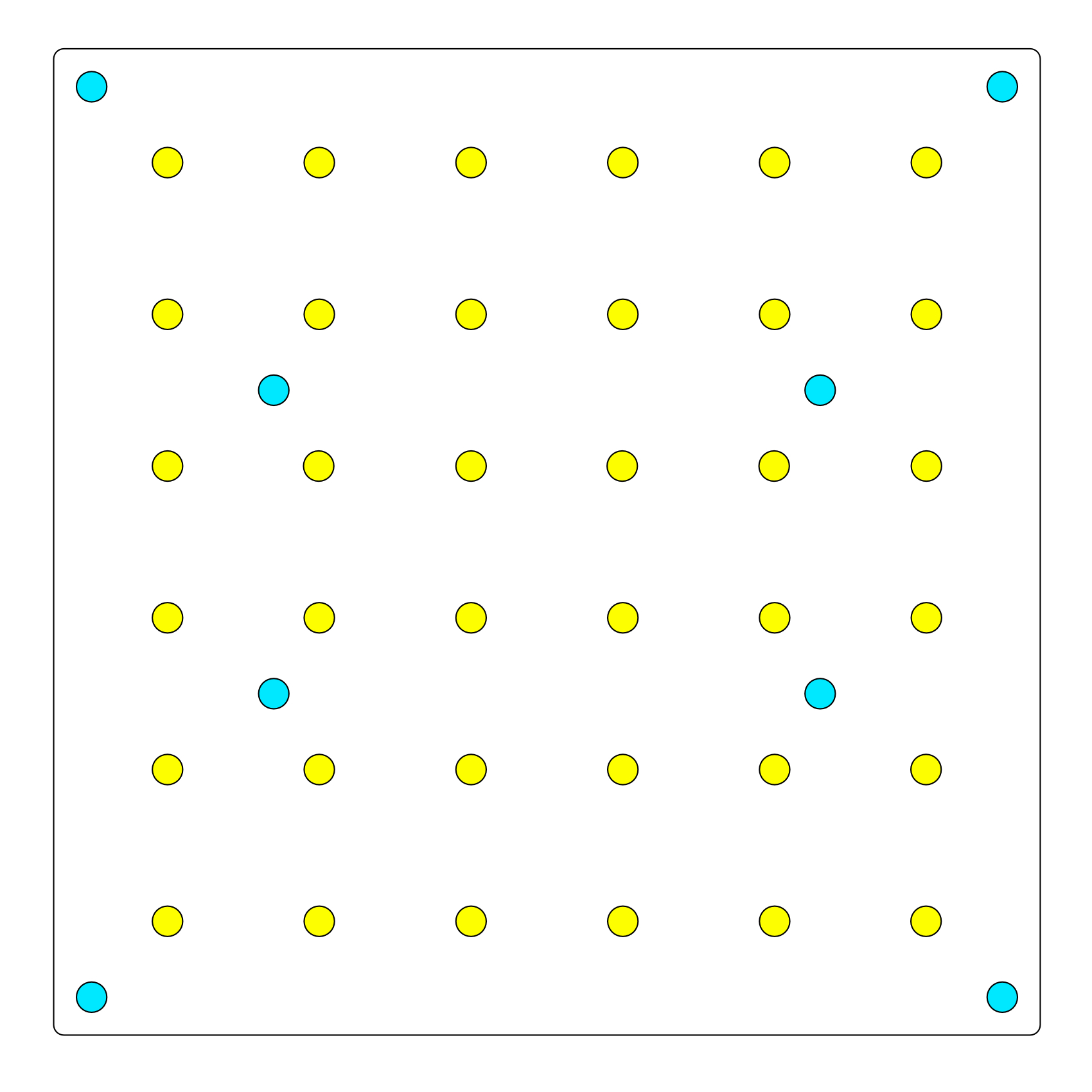
The blue coloured hole positions are the corner fixing points of my jigs and the blue internal four hole positions reflect the limits of where the table will be attached to the ‘Y’ axis rail. The yellow hole positions are the ones on which I would like to use Snapmaker and a ‘V’ carving bit to mark their positions on the metal plate I have made and will use them to hold to the table to the ‘Y’ axis rail.

I need to understand what the effect of bit size will have on my hole positioning, where there is some method to ensure that I can specify a 0.1mm point and depth. I will be happy to keep posting until the project is complete. The clamping system will be a simple vertical circular pillar with a hole through it and a flat filed on one side so that there is a clamping lip of a few millimetres to hold the workpiece without impinging excessively on the ability to CNC machine it.

4 Likes

More progress made. My new replacement pillar drill arrived yesterday but I spent all of my day fettling it. It needed some changes to the general assembly and I removed many PK headed screws and changed them for A2 stainless steel cap heads. I also added washers to the screws where they were bearing on plastic surfaces and then finished the added components with Nyloc type nuts. The nut has a deformable insert so they stay tight when first applied and do not unscrew because of vibration forces.

The noise from the motor sounded like bearings had been misapplied and it was a 5 speed belt driven machine so it should have run quietly, especially with a small (250 watt) induction motor. I realigned the motor and applied the correct tension to the drive belt. The machine now ran relatively quietly and the virbratory rumbling had gone. After assembling the B16 taper and chuck, I could not detect any runout so things were looking up.

I levelled the bed which can swivel side to side from -45 ~ 0 ~ +45 degrees. When checking the front to back levels, I could not get the table to align with the column. It appeared to be out of square, which is hopeless when trying to use a pillar drill. Its reason to exist is to drill exactly vertical holes. I had to disassemble the whole machine just to get to the column again. It was a steel tube inserted into a cast iron flange that was held to the base by means of three bolts. Further examination revealed that the column was not square where it met the flange. After a lot of bolting and unbolting the flange, I found a position where the column was square to the base and the table when it was all connected together. I am now happy that I have a quiet machine that is accurate when drilling holes without any visible runout.

The image below shows the drill press in situ.

The next task for the new table was to drill and tap it according to the plan uploaded earlier in this thread. I clamped the Snapmaker supplied table and my own blank table together. I wanted to ensure that the holes which I drilled would exactly follow the Snapmaker pattern at the extreme corners and where the table attached to the ‘Y’ axis rail.

The next image shows my new table blank clamped to the Snapmaker supplied table and then clamped to the drill table. I left the assembly free to move around the drill table until I located the hole I wanted to drill for threading then the assembly was clamped to the drill table. I used this method to ensure that the drill bit would not be pushed out of line by the hole not being on axis with the drill bit. The image shows the drill bit sitting in one of the four holes which are used to attach the table to the ‘Y’ axis rail. I was using the hole on the Snapmaker table as a guide.

The drill press kept the drill hole vertical and perpendicular to the drill table. A 3.2mm hole was drilled at a speed of around 2500rpm after applying CT-90 cutting oil. The process was repeated until all four ‘Y’ axis rail mounting holes had been drilled.

I kept the original table and my new table clamped together by means of threaded cap head screws because I had tapped the four corner screw holes first. The primary reason for keeping both plates together was that my taps would follow the threads in the Snapmaker plate and then when tapping my new holes, they would be perpendicular to the table. This would be the effect of using the Snapmaker table as a guide with respect to the hole positions and the tapping of a new threaded section in the newly drilled holes of my replacement table.

The next image shows the manual tap wrench and tap vertical and perpendicular to the screwed together table assembly.

Because I do not have access to an automatic tapping machine, I opted to tap all of the threads manually. This utilises a tap wrench and three taps. The taps are graduated and a screw thread will not usually fit the threaded hole well until all three tap grades have been used. One can buy drills combined with taps but it does not seem to be sound engineering to my mind. I have never broken a tap in my life but talking to people I know it appears to be very common. I guess rushing, wrong sized pilot hole, no cutting fluid and malalignment can all contribute to broken taps, The material plays a big part in whether taps will bind or not.

The next image shows the tap set for M4 threads and a countersink.

On the left is the countersink (Austrian made but excellent quality and only suited to slow speeds under about 700rpm) and then left to right are the three taps that normally make a set. The first tap is known as a ‘Taper’ and it has the position of starting the thread so it has a very long lead. The next tap is sometimes referred to as a ‘2nd’ or an ‘Intermediate’ tap. This one meets a little resistance with use and clears the previously tapped starting thread cut by the taper. It opens the internal diameter a little more so that the nominal thread size screw should fit, which is never usually evident with a taper. The final tap may be known as a ‘Bottom’ tap but more commonly in the UK, it will be known as a ‘Plug’ tap.

This has the cutting threads extending almost to the end of the tap and it usually opens the threaded hole to its final internal diameter. There may be a slight resistance felt when using a plug tap. What is important is that all three taps are used in sequence, kept perpendicular to the workpiece, used with cutting oil and an appropriately sized pilot hole. The tap must be backed off 1/4 turn for every whole turn forward. This allows the swarf to clear and the tap will never break if used like this. The image below shows the two plates clamped together by cap head set screws in the newly drilled and threaded holes. The tap visible is the taper tap and it has been used to the whole length of the tap. Nevertheless, at this point in the process and M4 threaded screw will not fit the thread. All taps ideally would be used to their fullest extent.

The final image shows my own table in situ and affixed to the ‘Y’ axis rail by the thumbscrews which were supplied by Snapmaker for the original table. Any questions are welcome.

3 Likes

A little extra work done today. The pattern of dots you see in the illustration below was what I submitted to Luban.

The dots are 1mm in size and I had wanted to use a V shaped carving tool to place the dots on the new table. I had expected the tool to just descend for each dot until the depth of .5 mm was reached. I was trying to produce a point that the drill bit would treat as a centre punched mark when it came to drilling the table. The carver wanted to produce very tiny circles and although it did each one in one pass.

This was not the effect I was trying to achieve. I was trying to get the tool to just touch the table and descend .5mm without moving laterally. In the event, I used the marks made as a location point for my automatic centre punch. The centre punched point was exactly what was needed to locate the drill bit correctly when using the pillar drill.

Here is a video clip of how the machine was working: Clearly it is describing very small circles rather than just making a point. At the last hole in the clip, the time the carver stays in the hole is twice as long as everywhere else. It reminded me of how slow it can be to stop a process that is running. Possibly the Snapmaker team could usefully look at providing a software interrupt command that stops the machine immediately and moves it to the origin set.

The next image shows the table with all of the CNC indents centre punched.

Following that operation the next thing was to use a drill press to drill all of the holes. I used CT-90 cutting fluid to make the job easier and to preserve the sharpness of the drill bit.

The next image shows a row of holes that have been tapped by hand. Once again I used CT-90 cutting fluid to make the job easier and to prevent the taps from binding.

The final image from yesterday’s work shows the table with M4 cap head set screws inserted in all of the tapped holes. The rest of the bed should be completed soon. There are 24 holes remaining to be tapped before I start on the clamps. more as it happens.

1 Like

Apart from the surface finish (which I will work on with some valve grinding paste and some autosol in an effort to make the 6061 T6 aluminium look a lot more homogenous) the machining work to my alternative SM1 table is now complete. All of the holes were drilled with a pilot drill of 3.2mm and then manually tapped with a series of M4 taps. My finishing touch is that the holes were countersunk for a better feel, to improve the lead-in for the set screws, appearance and to remove any possible burrs that could affect the leveling of the table. The attached image below shows what can be achieved with minimal work and a few hand tools. The only tool which I regarded as essential for this endeavour was a bench pillar drill, to enable me to drill perfectly vertical holes.

The notion behind this project was to provide a range of different points to which clamps could be attached. This would assist with setting up irregular shapes for CNC or laser work. The second part of this project is to produce clamps that will be very strong, will have a universal application method and will not impinge unnecessarily into the workpiece space.

My initial thought is to use aluminium rod to create my clamps. I envisage a rod of around 20mm in diameter with a flat cut or ground on one side of the rod, extending to two thirds or three quarters the length of the clamp. The untouched bit that is the full diameter would have a profile from the side that looked like a boot. A 4mm hole would be drilled along the length of the clamp at a centre of a chord at around 5mm from the edge.

This would leave about 3mm of metal before the hole edge. The flat would extend from the circumference of the rod to a chord of about 5mm. The total length would be around 20mm and there would be a need for 20mm diameter circular spacers of say 10mm thickness and these too would be drilled at the center of a 5mm chord. I would probably need to make other lengths of clamp depending on the workpieces i wanted to hold.

In any event each clamp would be screwed to the newly made table by varying lengths ofA2 Stainless cap Head M4 set screws. The spacers would allow different sizes of workpiece to be held and the clamp would only intrude 5mm into the work space and be incredibly strong and unable to be distorted by moderate clamping pressures.

Another refinement could be the use of soft facing materials on the clamping sections, which could do away with the need for sacrificial packing for the workpiece. That, at least is the intention. Next posting will be a technical drawing and then I can gather ideas as to the feasibility and usefulness of the design.

I have finally worked out the style and dimensions of the alternative clamp system I am hoping to make for my new SM1 table. The idea is that the clamps will be height adjustable by 10mm spacers and they will not hold the workpiece by more than the 5mm lip of clamp. The shape of the clamp body should allow many differently shaped pieces to be held. I am particularly interested in holding irregular shapes. I hope a significant advantage will be solid clamping without distortion of the clamps.

Any comments are most welcome.

1 Like

This is such a nice project… Can I add this link to the Snapmaker Original Question Guide? Thinking about adding a DIY section on there.

1 Like

Hello JKC20, Please go ahead, I don’t mind if you want to do that. I have not yet posted the images of the clamps working because I am still making them. I have also cleaned up the rough surface of the table so I do want to illustrate the bed and the clamps together while holding an odd shaped item.

1 Like