I have now completed the bed and clamp modifications for my SM1. My original feeling was that it was sometimes quite awkward to hold items to the bed when trying to use the CNC milling functions for SM1. One limitation that I ran into very quickly was the 90mm square workpiece limitation. I assumed that this was partly due to the travel of the head and the length of the clamps that were supplied with SM1. The illustration which follows shows the clamps which were quite long and quite soft and they marked easily and bent under moderate clamping forces as well as leaving clamping marks on the workpiece.

Another limitation which I ran into was the placement and number of the screw holes in the SM1 table. The illustration shows just 4 screw positions are available, starting 5mm in from each corner. If the most central holes had to be used, the workpiece would have to be very small to fit inside the dimensions permitted by the screw holes. The dimensions of the table were fixed at 130mm square.

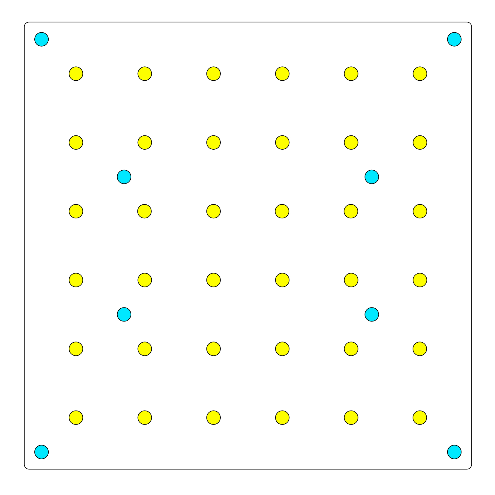
I planned to make a new table and to permit it to have a few more screw positions. The table was to be made from 6061 T6 aluminium so that it had good resistance to bending forces. I used a 4mm thick sheet so that the size was no different in thickness than the existing table. In my mind I had wanted a table that would permit me to clamp items from many different points, not just the corners. My thinking was that this would permit odd shaped items to be held securely for CNC milling. The illustration shows the proposed screw holes in yellow.
The blue holes in the corners are as they were in the original table and the central holes in blue are for fixing the table to the ‘Y’ axis rail with the supplied thumb screws. Many a time when removing the table to change a jig, I wished for a more convenient system. The SM1 machine has to be removed from its enclosure and tilted so that the thumbscrews can be reached. Some sort of easily accessible toggle clips would be a better solution than this method.
The new plate was drilled, countersunk then tapped for M4 threads and polished to remove many of the marks left by machining. A couple of mops using tripoli compound and white rouge were used for polishing.

Along with the improvements in the SM1 table, I chose to redesign the clamp system. It had to be versatile and strong and be small enough to permit a larger work area for CNC milling than 90mm square. It also had to be helpful when trying to clamp irregularly shaped workpieces. The next illustration shows what I had planned to create from a piece of 6063 T6 aluminium tubular bar.

With my clamps completed i added a finishing touch of 1mm of cork to the clamping surface. The thinking was that it would preclude using various bits of packing and keep the clamp dimensions small, My clamp design was to use the smallest possible clamping area. I had thought that a semi-circular protrusion extending just 5mm would be workable. I placed the hole for the screw off centre to increase the ease with which irregular workpieces could be held. With enough holes in the table, I could clamp many different styles of workpiece securely while still keeping the clamps out of the pathway of the milling bit.
The next illustration is an irregularly shaped workpiece of 120mm in length and 90mm in width and 38mm in depth, clamped with just 4 clamps to my new 130mm square table. The workpiece is held securely and could be CNC milled to any point that is just 6mm inside of its edges.

It is worth noting that although the workpiece is soft pine and it is held very securely for milling, there are no clamping marks on the workpiece, as is shown in the following illustration.

The clamp had to be strong so that it would not bend under moderate or any pressure. The following illustrations show the clamp detail. Very poor jpeg images so the quality is not great.


I am not sure how long the self adhesive cork will last but I will modify it as and when necessary. The whole project has taken a while because I do not have many machine tools. I used an engineer to shape the clamp bodies because I had no milling machine. The drilling was easy and countersinking was also easily achieved. The parting tool which was used was done at the engineering company because I have no lathe.
What I have learned from this is that consideration should usefully be given to how any tool may be used. I think the SM1 bed did not follow what appears to be normal practice for clamping options for this type of machine. Being new to this whole world of 3D/Laser and CNC work, I had little idea of what was needed. Within a short time of use, I found myself brushing up against the limitations imposed by the design of the clamps and the table of SM1. I have learned a great deal while modifying my machine and I feel that I have now extended its usefulness.
The clamp design makes sense to me because it can be extended to cope with other material sizes that are irregular in height. I have created some 10mm thick drilled spacers that can raise the clamps. I have numerous lengths of M4 cap head set screws so that the screw does not have to protrude through the bottom of the table but it can remain within the threaded 4mm thick portion of the table.
Edit: I forgot to include the 10mm spacer so to complete the project here are some additional pictures. The first image compares two clamp bodies (from the side) for length where one clamp has the additional 10mm spacer attached.

This image shows the circular spacer attached to the clamp from the front. It also shows the line scribed for me to file the flat on it.

The next image shows the spacer with the scribed line in a vice ready to file the flat.

The final image is the spacer after filing.
Any questions are welcome and I will do my best to answer them.


