I printed the print after performing the automatic leveling.
The right side of the print is well adhered to, but the left side is just barely adhered to.
Sometimes the print fails due to failure to adhere.
From this situation, I can’t say that the automatic level compensation is working well.
Is there a bug in the compensation function?
If there are no bugs, I would like to see more detection points and other measures taken.
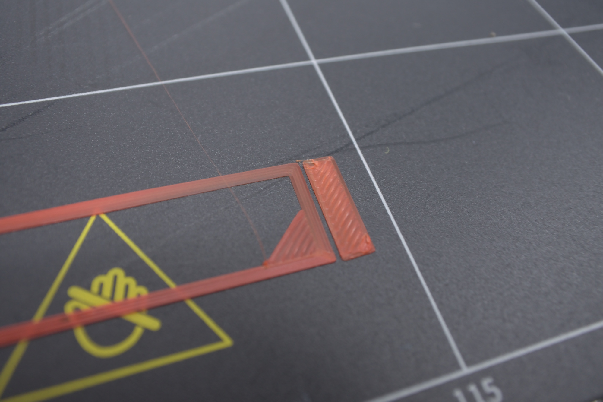
A straight-edge ruler revealed the light on the other side.
You can see that the bed is curved.
It coincides with the weak adherence of the filament.
I think the auto-level adjustment is not working properly.
I decided to check the trusses if all the holes to which the heating table is screwed are at the same height.
As you can see in the attached video there is a problem. When tightening the screws from the heating table, in places where these holes are located lower, the table top is bent, which probably affects the flatness of our table.
I have been struggling with this problem to this day since I received the device. Small prints come out OK, but I can forget about larger ones for now - too big difference in flatness. And I also have the impression that auto leveling is not working or not working properly.
Currently I have an updated machine to version 1.10.1 and Luban 3.12.2.
This isn’t an auto-level problem; it’s a problem with the underlying accuracy of the machine.
The result of the auto-leveling measurement is a bilinear function in X and Y. This class of shapes are hyperboloid. They are capable of compensating for only two deviations from ideal:
Tilt in the bed. This is when the average surface normal isn’t quite vertical.
Twist in the bed. This is when the edges of the bed are not quite parallel, that is, they don’t lie in the same plane.
Smaller deviations, such as the one you illustrate with your picture of a straightedge, cannot be corrected with the current software. At the very minimum, you’d need far more sampling points. Your photo shows deviations from straight with noise features around 10 mm in size. You’d need sampling, at minimum, at half that size to be able to have any hope of correcting it. As an estimate, that’s (330/5)^2 sampling points, or something over 4000 points. If you assume it takes 1 s to sample each point, sampling for calibration would take 2.9 hours. To make matters worse, because the way that the bed is mounted, it’s going to move each time you take it off and remount it. To get anything like 1 s sampling, it means you need an automatic digital measurement system, which could be implemented as a separate work head in an ideal world. The cost of this head would be some small number of hundreds of dollars.
The easiest way to mitigate this is find the flattest part of the bed and print there. Related to this is print in the center of the bed, because it’s more mechanically stable there (less rotation around the axis formed by mounting to the Y-axis linear modules).
Secondarily, planning on printing on rafts, which have the benefit of using plastic fill to provide a level printing surface.
This is basic design problem with the way the headed bed is affixed to the subbase. They use screws with cone-shaped heads and cone-shaped countersinks. When you screw down one of these, the head and countersink act as a pair of wedges. Downward forces on screws with any inaccuracy in hole location converts into sideways forces within the bed. These tensile and compressive forces cause buckling of various kinds within the bed material.
Inaccuracy in hole placement is inherent in a heated bed system because the temperature of the heated bed changes, because the temperature of the bed and subbase are not identical, and because their coefficients of thermal expansion are not the same. At best, if the underlying supports were completely accurate and flat, you’d be able to operate at exactly one temperature at a given ambient temperature.
The sounds-easy solution is to eliminate the wedge but using pan-head screws and counterbores so that you get a flat mating surface that doesn’t generate sideways internal forces. The heated bed material, though, is too thin to make an actually-easy.
So there is a design problem with the hardware.
It’s not something that can be fixed by replacing parts, so the only way to fix it is with software.
The calibration can be done automatically, so it doesn’t matter if it takes several hours.
It’s just a matter of allowing the user to choose which accuracy to calibrate.
3x3, 5x5, 8x8, 10x10, 15x15, 20x20 …
It would be nice if the estimated working time was displayed on the touch screen.
I think this is the happiest solution for both the user and the manufacturer, what do you think?
There are many parts of the bed that are not calibrated to the right or back of the bed with the current calibration.
I would like to see every corner of the print bed targeted for adjustment.
You can choose arbitrary grid sizes up to 11x11 if you perform the calibration via a laptop terminal.
If you want to compile your own firmware you may be able to use larger than 11x11 as it’s a firmware constant GRID_MAX_NUM that can be changed. There will be a limit at some point, I don’t know if it’s actually 11, I suspect it can be larger.
Thanks for your comment.
I read the link and it’s a bit difficult for a beginner like me.
I think it should be implemented in firmware to make it easier for everyone.
I don’t think we need an animation on the touch screen to show each point in the calibration.
I think it would be better if there was a progress indicator like “1/121”.
It might be able to be fixed only with software. I don’t know enough about the proximity sensor in the FDM head to be able to say, but I do get the impression it’s not high resolution, nor may it be particularly repeatable. It might be accurate enough to gather the data you need; it might not. These machines are not known for high-quality attention to detail, so there’s a real question about whether it even could work.
As for me, I’m going to focus on mechanical means to make a flatter bed. That’s higher impact for my personal time than to go down a risky path to reuse a hardware element that might not even be up to the task.
Even though this is more points, the correction that applies is still a bilinear function, so it remains only able to correct the deviations I mentioned about. What more points gives you is more accuracy in the coefficients calculated for the correction.
In order to do better, you need a different mathematical model for the correction. If I were doing it, I’d use a set of Bezier patches interpolated from the sample points. These are cubic polynomial functions that can be patched together with matching first derivatives.
I think bilinear interpolation offers the best tradeoff of functionality with required computation.
At the end of the day, even with bed leveling, you still have a non-flat surface on the bottom of the print, and also the top since Z fade out is necessarily disabled due to how SM handles the mesh. The history of bed leveling implementations is in correcting small deviations, on the order of hundredths to tenths of a mm, and in that range bilinear performs great.
The snapmaker bed unlevel is on the order of tenths to full mm’s. Any sort of bed correction in software is misguided until the bed can be made more flat, and at best is a false sense of security.
The choice of bilinear by Marlin was due primarily to compatibility with 8 bit controllers, such as RAMPS. These microprocessors are computationally limited and all moves must be straight lines. Bilinear interpolation is a nice fit here because the start and end XYZ coordinates can calculated in advance at the time of parsing the gcode and entering the move into the planner. The motion ISR then steps the axes at a constant rate until the destination is reached.
Bezier curves would need to be recalculated at every ISR step. This is already being done for acceleration, as S curve acceleration is enabled, however at 120MHz with a 32bit processor it’s much less of a hit.
Regardless, the effort spent implementing Bezier bed leveling would be better spent making a flat print surface so that bilinear would be effective. The presence of the mesh bilinear correction is already an ‘olive branch’ of sorts from the Marlin team to cheap printers where the more ideal 3 point bed tilt measurement is insufficient. The goal should be to disable mesh and enable matrix rotation via the 3 point method so dimensionally critical parts can be printed with ease. A glass print surface allows that.
I also think bilinear correction is enough. Perfect correction is difficult to do.
I think it’s relatively easy to increase the sampling points in the firmware, but I wonder if the manufacturer is not going to support it?
I’d like to try Tone’s method, but I’m not sure about it as a layman.
If it gets damaged, it’s at your own risk.
I sincerely hope that the firmware will take care of this.
I also have the glass I used in my previous printer.
But there is no good way to fix the glass and build sheet to the SM2.
It is, so I did. Max I can comfortably get is 21x21 before the chip runs out of RAM; it can’t hold all those mesh points in memory, just not free space in the 98k of RAM.
That’s not really within an order of magnitude of what you need, unfortunately.
Binder clips. Unless the glass it way too small? In which case, for a test, you could move the glass into a corner and use 2 clips on the left, 2 clips on the front, it might hold it down well enough, even with nothing supporting the opposite corner? Maybe just tape that corner down?
Or just tape the glass plate to the existing removable build sheet with painters tape for a test?
If you do that, don’t forget to M420 S0 to disable the bed mesh unless you’re planning on recalibrating (glass size dependent, would have to be manual, auto won’t pick the glass up). Doing so can abruptly cause the nozzle to move up or down, don’t do it near Z0. I’d do it immediately after homing. You will need to very slowly move down to the bed as just going to Z0 will crash 6mm below the bed surface. Once you’re at the correct Z height with the card issue a G92 Z0 to tell the machine that it is now at Z=0. That will be temporary until you power off or reset the coordinate space. M206 Z## would make it permanent.
I’m not sure why you thought that, eh9’s post?
I’d be happy if it goes to 11x11.
If you can compensate with 21x21, that would be great.
My printer is located away from my computer.
Is it dangerous to work remotely over WIFI?
Are the working procedures correct with the following contents?
1)Issue the M420 S0 from the Luban console.
2) Gently lower the print head near the bed and use the calibration card to adjust the clearance.
3)Issue G92 0 from the Luban console.
4)Issue M206 Z## from Luban console.
What should be specified in the ## part?
Also, to return the printer to its original state
1)Issue the M420 S1 from the Luban console.
2) Run auto calibration.
More like effectively impossible. Luban doesn’t show responses on the console unless you have a wired connection. (No one seems to be able to explain why they thought this was a good idea.)
If you’re printing on a surface with high flatness (such as glass), the difference between 5x5 and 11x11 sampling mesh is small. Aggregate accuracy of multiple samples goes generically as the square root of the number of samples, so you’ll decrease your error by a factor of two (approximately, it’s 11/5) at most. And this difference matters most only for first-layer adhesion; if that’s working well, there’s no need to put in effort.
To do an 11x11 grid you’ll do the following steps. This can be done over wifi as you don’t need a read back.
G1029P11 ; Define 11x11 mesh size
G1029A ; Run auto calibration
After that completes it will leave the nozzle near the center waiting for you to set the height with the calibration card. Use the jogging controls via Luban or via the touchscreen. Don’t move in X or Y, only Z, and do the normal light tension on the card.
Then finish with these commands:
G1029S ; Offset matrix by current Z position
G1029D0 ; Compute interpolations and enable bed leveling
Hey @eh9, check out what I just found. When you do an M420 V there’s an “interpolated” matrix that’s a higher density than the raw measurements. Never really understood that until now.
Each calibration point is subdivided by a factor of 3 and interpolated using the Catmull-Rom spline method.
That’s part of the limiting factor in RAM usage, doing a 21x21 grid is interpolated up to a 63x63 splined surface.
Would be interesting, for people who would prefer, to disable the subdivision and probe a higher density. I was able to compile up to a 61x61 grid by setting the subdivisions to 1. However that’s using 98.3% of the RAM at time of compile, it likely will go over in actual use as FreeRTOS allocates dynamic memory for ports.
Disabling interpolation entirely is a bit more tricky, but it frees up more RAM and the number of grid points can be expanded to 83x83
That would be useful for doing PCB routing, where the practice is to adjust Z-height on the fly to match the actual surface. You’d need to be able to specify a different bounding box, but that’s easy by comparison.
I have a long term project involving getting a digitizing touch probe working. I think for me, the time spent probing the surface of the PCB to generate a compensation mesh would be better than trying to get an on the fly laser correction working.


")