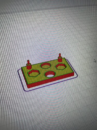
I print 0.2 mm smaller than the solid measurement

I use a Snapmaker A350t. In the past, the 50 mm solid drawings I drew were printed at exactly 50 mm size. As time went on, I continued printing parts that didn’t require measurements. I bought Iglidur i190 filament. I was aiming to print professional parts with it. However, the nozzle clogged. So I replaced the nozzle. Since I was starting out, I decided to print a measured part. However, the 50mm solid model printed at 49.8mm. As a mechatronics engineer, I couldn’t stand this. :slight_smile:

I proceeded by eliminating the possibilities.

  • I replaced the hot end entirely with a new one.

  • I removed the two rails that move the hot plate and reassembled them in their home position.

  • I updated the firmware and re-did the entire setup.

  • I deleted and reinstalled the Luban program.

  • I chose a time cooler than 30°C to avoid the summer heat.

The print piece shrinks by 0.2 mm in all directions. However, the holes are the exact size. Therefore, I cannot enter the shrinkage ratio. Why am I printing at 49.79 mm, while the pieces I made before were 49.99 mm?

I used two different brands of filament. I bought both filaments, opened them from their vacuum bags, and printed directly without drying them. However, I’d never drying before. The only possibility I haven’t tried is drying.

If anyone wants to help, I can send you photos of my experiments.

I found this video very insightful: Calibration Cubes are BAD! This is how you calibrate your 3D Printer — CNC Kitchen - the TL;DR: Do not try to calibrate your printer, try to calibrate your filament profile, which may be necessary for each spool. In the video there’s a calibration object suggested that should help you to get better results.

1 Like

If there is a customized calibration process for Snapmaker, I would appreciate your help.

The solutions in the video aren’t real solutions.
(For Snapmaker. I wish I had bought a bambu lab printer.) They require adding x/y coordinate tolerances for each print. The only adjustment in the filament settings that can make a 0.2mm difference is the shrink ratio. However, even if it reaches the required size for this part, the size distorts as the part getting bigger. I’ve been printing test pieces since this morning. When I ran the filament idle, I measured 0.5mm instead of 0.4mm. I also used 0.5mm for the outer wall dimensions instead of 0.4mm because the only part I think is printing incorrectly is the outline. This reduced the outer dimension to 49.7mm. The holes have grown to 10.1mm. Tomorrow, while using all the standard settings, I’ll try changing the outer wall thickness to 0.3mm.

Printing a wall of 0.3mm with a 0.4mm nozzle is not as precise (in shape or straight) as printing 0.4 or more.
This comes from pressure in the nozzle which causes a proper (no under-) extrusion.

i would simply adjust my flow offset for each filament by a tiny amount to get the correct outer measurement.
Dor the inner holes or shapes i would compensate the hole size.

1 Like

The flow settings and all other adjustments didn’t work. I tried as you suggested. There are no errors in the internal holes or their positions. The only error is that the outer walls are printed 0.1-0.1 mm short. Isn’t there a way to just thicken the outer walls?

Rescale the model by +1% for example?

The more interesting part is this:

I found a G code on the forum: Heat Tower. When I run it, the width of the heat tower is exactly 10 mm. Could you please create a G code for a 50x50x50 cube using the standard settings you always use?

I’d like to try getting a G code from someone who has printed without any problems. Maybe I can figure out the problem by comparing it this way.

During my experiments, the exterior walls, shown in red on the Luban screen, consistently appear 0.2 mm too short. I suspect there may be a problem converting to STL format with SolidWorks. So, I’m testing again in AMF format.

Standard PLA settings are 215°C. The default print setting is normal.


I tried different formats, but the result is the same.

I downloaded the Snapmaker Orca beta and tried it. The result is the same. I’d like to ask someone who performs precise measurements with PLA in Luban to create a G-code for a small part.

Would you mind to share the object? I admittedly never cared about dimensional accuracy too much before, but now you made me curious. Only caveat: It may be a few days until I have results, currently not too much time at my hands.

And: The Snapmaker linear modules have a tendency to get their sliders loose, which causes backlash and dimensional inaccuracies. The Cauliflower pattern from the video should be able to detect this. Re-tightening the sliders helps a lot.

TestParcası.STL (51.5 KB)

If you create a G code with your own settings via Luban using Pla filament, please share it with me.

OK, had a bit of unexpected time at my hands and sliced and printed your model - used Cura, not Luban, hope that is still OK.

Setup:

  • SM2 A350 (Kickstarter version)
  • Dual extruder
  • 0.4mm brass nozzle
  • White PLA (Formfutura rPLA)
  • 200°C nozzle
  • 60°C bed
  • 0.2 mm layer height
  • 60 mm/s speed
  • 4 bottom/top layers
  • 4 wall lines
  • 25% grid infill

Here are my dimensions (measured with a good ol’ mechanical caliper with nonius, 0.05mm scale resolution):

  • width: 49.95 mm
  • breadth: 30.00 mm
  • height (base) 5.05 mm
  • pin diameter (thick part): 4.95 mm - both
  • pin diameter (thin part): 2.00 mm - both
  • pin height (total): 14.95 - 15.00 mm (left/right)
  • Through hole: 9.85 mm - 9.90mm (x/y direction)
  • Half-through hole: 10.00 mm
  • Depth of half-through parts: 3.05 mm (all three the same)
  • Hex breadth across: 9.90-10.00 mm, dependent on direction measured

Honestly surprised and pleased how precise this came out. GCode attached. Should also work with single extruder.

The round holes are the most problematic, I have a bit of inconsistent extrusion there, perhaps my retraction settings need tweaking.

S2ADE_TestParcası.gcode (837.2 KB)

2 Likes

Let me tell you what I did during this process.

I previously thought the extruder might have been out of calibration due to a clogged nozzle. I calibrated it. I even designed a tool to do this. I’m including the STL file here in case anyone wants to use it.
Ahmet.STL (15.2 KB)

After calibration:

  • Default PLA filament settings
  • Using the Normal print option in the Luban program,
    I achieved a measurement of 29.90 mm (205°C).

At 215°C, I achieved a measurement of 29.95 mm.

However, when I increased the speed, that is, the fast print option, the measurements returned to 29.82 mm.

This further confirmed my suspicions. There was a slicer problem.
A calibrated and oil-maintained machine should have no errors.

Thanks to a user named Hauke, I confirmed my suspicions. Thanks to the g-code he generated with Cura, I was able to achieve a very fast output and close to 29.98mm. Thanks, my friend.

From what I’ve read on the forum, dual extruder owners don’t need calibration. However, I recommend calibration for single extruder owners.

Based on this experience, to increase the outer dimensions without distorting the coordinates on the part, 205->215°C creates a 0.05mm change.

While experimenting with the flow, suggested by a friend named xchrisd, I discovered a section on Luban where I could only manipulate the flow of the outer walls, and I tried it. By setting the outer walls to 115% flow and the inner walls to 110% flow, you can achieve an outer dimension expansion of about 0.1mm. However, this makes the edges look very unsightly.

In conclusion, although my extruder calibration hasn’t been good in the past, with recent updates, a discrepancy has appeared in the Luban software with the Snapmaker A350. This error is exactly 0.1 mm. Even with a calibrated device, it has a 0.1 mm deviation. I don’t know how to report this information to the authorities. However, until a solution is found, I recommend using a different slicer.

1 Like

This matches my experience. The SX default flow rate leads to underextrusion, while the DX factory setting for me is spot on.

Important to know: Some firmware updates overwrite the user-set value - so after each firmware update double check that your custom flow rate is maintained!

Write a mail to support@snapmaker.com.

1 Like

Why are you so determined that it is a “G-code” or Luban error?
I see no mention of XYZ calibration here using M92.

1 Like

Because with the same stl file I get 29.90 mm with Luban and 29.98 mm with Cura.
However, if you could give me information about XYZ calibration, I would like to do it to make it perfect.

This really is the first thing to check, before messing about with G-codes and extrusion %.
https://teachingtechyt.github.io/calibration.html#xyzsteps
Carrying out the above is fiddly because of the mounting of the dial gauge - you need a sturdy mounting so that there will be no flexing. And I found the cheaper digital gauges have not got great repeatability and will give you a different zero point every time you return the head to your start position.
Making sure the mechanical movements are correct is the most basic calibration, but should follow any backlash checks.

Solid objects or filled objects will have more shrinkage, so it’s better to print a hollow, single wall object as large as you can to get a more accurate correction ratio, such as a large square or rectangle. Leave this stuck to the bed and measure it in situ.
But if you’ve got an error of 0.2mm on a 20mm cube and an error of 0.2mm on a 200mm object then you have backlash or extrusion volume issues and it’s unlikely to be be caused by mechanical movement inaccuracies.
Think about this: you have a 0.2mm error overall in width, so you want to add 0.1mm to each side of the object. So you think to make the wall 0.2 wider will squirt 0.1 more either side of its track, and it does this both sides of the object, theoretically adding 0.2 to your overall dimension.
But does it? It doesn’t know you are trying to compensate for an overall size error, it only knows you want thicker walls. But it doesn’t plan on giving you a wider object as it will compensate for the thicker walls by moving the track it follows further inside the object.
In the above example it will move its track 0.1mm further inward, theoretically giving you the same external dimension that you were trying to correct. I suspect Luban and other slicers handle this adjustment in different ways, therefore giving different results. To pursue this correction further would be just ‘chasing your tail’.

1 Like

This is after you tweaked settings in Luban? The Luban cube looks well within tolerances now!