Hi Folks,
Just thought I’d share my learnings from carving a 3D figure using the CNC without a rotary module. I’m new to CNC operations, and I searched far and wide online, but couldn’t find a complete workflow described anywhere.
The project:
CNC carve a 3D replica of a Roman statue of Aphrodite using a piece of timber.
The Method
- Use Fusion 360 to model the statue (I imported an STL from Thingiverse)
- Design and build a jig to hold the stock
- Use Fusion 360 to create the CNC tool paths
- Carve the front side of the statue
- Turn the statue face down
- Carve the back side of the statue
The Workflow
Fusion 360 Design Mode
- Open STL file representing the model in Fusion360 (free version)
- Model the stock in Fusion360 (in my case, this was a length of 30x40mm Tasmanian Oak, dressed all round.
Take into account the fact that you need to clamp the stock beneath the statue - e.g. if the statue is 10cm tall, model the stock to be ~15cm long so that the base of the statue “grows” out of 5cm of stock that you’ll use to clamp, and also to set work origins and ensure alignment when you flip the work.
- Create a sketch on the upper face/plane of the stock. Place a sketch point on the midline of the stock about 2cm below where the base of the statue will start - this will be your work origin.
- Project the point from step 3 onto a sketch on the bottom face/plane of the stock - again, this will be your work origin when you flip the piece. Both sketch points should be on the midline, and exactly the same distance from the end of the stock.
- Scale and orient the model so that it just fits inside the stock. (Note: you may need to enable the experimental mesh features in F360 to scale the mesh). You should have the stock lying flat on the XY plane - and the model oriented with the stock such that the Y axis represents her height (head to toe), X axis represents her width (shoulder to shoulder)
- Design a jig to hold the stock - I based mine on a 3mm sheet of MDF, with a rectangular cut-out perfectly sized to hold the clamp-end of the stock. (Basically a U shape with square corners). The purpose of the jig is to ensure exact alignment of the stock square with the X & Y axes of the work table.
Fusion 360 Manufacture Mode
This assumes that you’ve already set up Fusion 360 to work with Snapmaker - i.e. imported the tool libraries etc. That process is pretty well documented on the Snapmaker forum. I’ll also assume you know the basics of generating a tool path, exporting G-Code, and running the g-code on your SM. You MUST master these steps before messing with 3D CNC.
- Create a new setup, define the stock for the jig. (If you don’t yet understand setting WBS origins etc,
- Use 2D contour to build tool path for cutting out jig.
I found the mills that I bought from Snapmaker were a bit too delicate for the combination of hardwood and my clumsy novice CNC skills, so I invested in some bigger ones - 2mm and 3.175mm straight cut mills, as well as some bigger ball mills.
- Generate the tool path to cut the jig
- Create a new setup for the model. Define the stock dimensions to match the X & Z dimensions of the stock (i.e. width and height of the upper face from the work surface). set the Y dimension to the height the model + 5mm i.e. if the actual stock length is 15cm, and the model is 10cm tall, your Y dimension is 10.5cm. Adjust the Y offset so that the stock totally contains the model, with about 5mm protruding above its head. (This constrains the tool path to the section of stock we want to carve - the bit where the statue will appear).
- Set the WBS origin to “model point”, and select the origin sketch point from step 3 above.
- Ensure the axes are correct.
- Define the depths: bottom should be slightly deeper than .5 times the Z dimension of the stock, top should be the stock top.
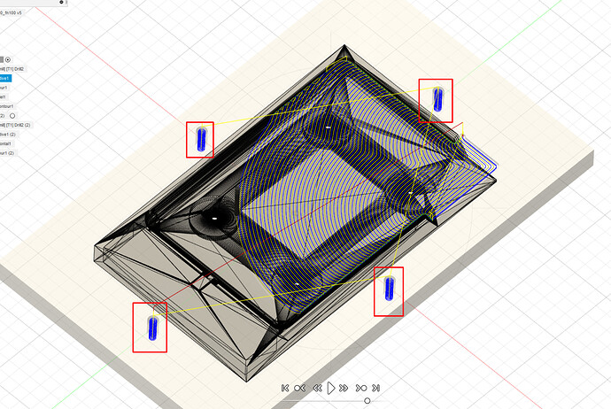
- Define the first tool path: I used 3D adaptive clearing with a straight cut mill. Be sure to “leave stock” - e.g. I left about 1mm for final removal with a gentler process and tool.
- Generate the tool path and simulate to check for collisions etc.
- Generate a derived operation for the second tool path - I used 3D modified spiral with a ball end mill. ensure REST machining is enabled. This ensures the second tool path knows what material remains from the previous operations and avoid collisions and unwanted air cutting.
- Repeat 8-10 for generating tool paths as needed to get the level of precision you want.
- Export your G-Code for each tool path.
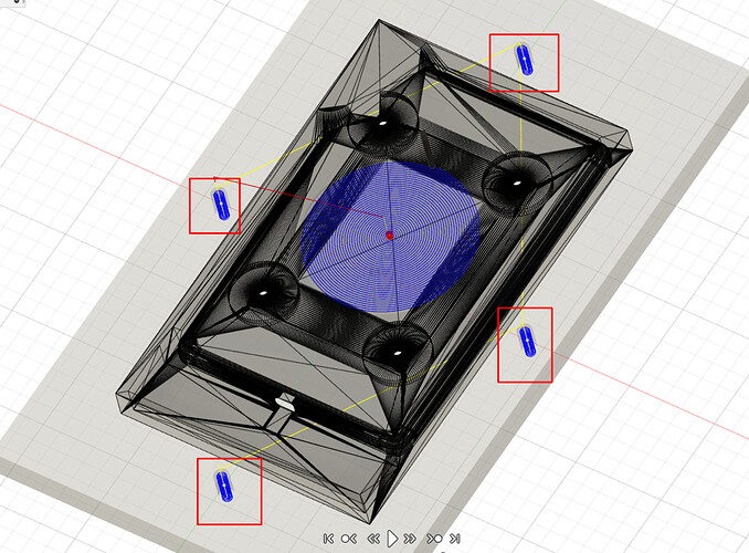
- Create a new setup with the same parameters as step 4, except: reverse the Z axis and the Y axis, and check that the bottom depth is now slightly less than .5 times the Z dimension
^This basically tells Fusion that it will now be cutting “up” into the piece from beneath the work surface. The resulting G-Code will allow us to flip the workpiece and cut from above. - Make sure the WBS origin is set to the origin point on the lower face of the stock.
- Repeat the tool path generation steps 8-12. You’ll probably want to use smaller step-downs and slower cutting rates for this side since the model will have less support and will be subject to bending/vibrating.
- Check the simulations - you should see the tool cutting upwards from below
- Export G-Code you’re ready to start cutting.
Snapmaker
Tip: for best accuracy, turn the SM off and “tram it” by manually moving each axis to its limit to overcome skipped steps on the actuators etc.
Mill the Jig
- Clamp the jig stock on the work surface
- Set the work origin (I’ve not described a specific work origin for the jig - make your own decisions)
- Raise the toolhead so that it clears all fixtures.
- Load the jig g-code
- Run boundary - check for collisions
- Start job
Mount the Jig
- Attach your new jig to the wasteboard. Make sure it is square with the X&Y axes such that when you place the stock in the cutout, the stock is perfectly square with X & Y, (remember, the Y axis will be the head-to-toe axis of the statue). I used painter’s tape to secure my jig, and clamps to secure the stock for carving.
Prep the Stock
8. Prepare your stock: cut it to an appropriate length - height of model + a few mm overhang at the head + ~5cm for clamping beneath the base of the statue. Make sure the base is cut square (i.e. all angles 90 degrees)
9. Measure and mark the centreline on the upper and lower faces of the stock
10. Mark the origin point on the centrelines - refer to the stock you modelled in the design mode of Fusion for measurements.
Mill the Upper Face
11. Place the stock in the jig with the clamping end of the stock up against the base of the “U” cutout.
12. Clamp the stock securely - I used two clamps on the upper face at the clamping end, and two clamps pressing against the sides of the stock at the other end.
13. Set work origin to the origin point marked on the centreline
14. Raise the z-height to clear all fixtures.
15. Load g-code and run boundaries
16. Run the job, rinse and repeat for the other g-code files for top side of the statue
Mill the Lower Face
17. Rotate the stock around its Y axis so that it is now face down with the clamp-end sitting snugly in the jig again.
18. Clamp the stock securely in the jig. It may be necessary to place some support materials under the upper part of the model, but be careful to keep it lower than the “bottom depth” you set in step 13 of the Fusion360 setup.
19. Set the work origin to the origin point marked on the centreline of the stock.
20. Raise Z height, load g-code and run boundaries
21. Run the job.
Final thoughts:
- The accuracy of the carving depends very much on accurate measurement of the work origin, and accurate alignment in the jig.
- This approach is quite effective - it carved almost all features with a high level of detail, however there were a few facets that the tool cannot reach from the Z axis due to other parts the model blocking the tool path.
- It is possible to carve the sides using the same principles - do another setup in Fusion, redefine the X axis as the Z axis, etc. etc. Doing this requires very careful attention to accuracy - I rushed it and ended up removing too much material.
- If the model lacks support - e.g. during carving of the reverse side - you need to greatly reduce the cutting feed rate and step-down depths compared to normal. Otherwise you get tool chatter and flexing of the model resulting in poor finish and/or artefacts.
- For simpler models, or for larger production-runs, look up double-sided CNC jigs on YouTube for more sophisticated approach to jigs and alignment.


