Generating CNC G-code that doesn't do unnecessary work

I’m new to CNC, so please bear with me here.

I have an STL model generated by OpenSCAD that I have already used to do 3D printed draft versions of two mechanical parts that I need to fabricate in very small quantities (like 1 each). My goal is to cut the final versions of these parts out of an 8mm-thick sheet of T6 aluminum using the 200W CNC module. Unfortunately, I’m running into a few sharp edges in the software that I’m not quite sure how to solve.

The biggest issue I’m running into is that the toolpath that Luban generates is incredibly suboptimal, removing far more material than is actually needed. Like 10,000x as much material as is needed.

The model I’m trying to mill consist of two separate pieces that are roughly U-shaped. That means there’s an area in the middle that isn’t part of either model. That area is roughly plus-shaped, and is 120mm x 80mm, the center of which is a roughly square area that’s roughly 40mm x 80mm, for a total of almost 50% of the 120mm x 120mm part of the plate that’s I’m actually working with.

The model is, in fact, entirely flat, with the exception of some bore holes, which need to be bored at a small diameter for the screw and a larger diameter partway through the material to accommodate the head. Were it not for that, I’d just use an SVG file and tell it to do cutting, but it insists on treating this as carving because I’m starting from a 3D model. I’m not sure if this is a problem or not.

An optimal toolpath would cut out a single path that’s as wide as the end mill, removing just enough material to separate the part that I want to keep from the rest. This would result in cuts totaling somewhere on the order of 800–1000 mm in length.

But does Luban do that? Oh, no. Luban chooses to grind away everything that isn’t supposed to be kept. The result is a lot of unnecessary cutting because of the shape of the model. We’re talking about 1.3 million lines of g-code here, the overwhelming majority of which involves going back and forth hundreds of thousands of times to grind away those huge areas of unused material that could just as easily be left alone.

The same is true for the two large holes in each piece, though that’s at least a more tolerable amount of material than the space between them.

Compounding this is the fact that it needs to drill five bore holes in extremely precise spots, which requires the use of the 1.5mm flat end mill, and I’d rather not try to change bits out in the middle if I can help it, which means that removing so much material is a huge problem.

The result, of course, is a model that is estimated to take 55 days to carve. Slow doesn’t begin to cover that. And maybe I’m being way too conservative in the stepdown, stepover, plunge speed, and work speed numbers, but even if I could speed things up by an order of magnitude, the amount of time would still be absolutely nuts.

The second problem is that it isn’t adding cuts all the way around the pieces, instead leaving one entire side of the pieces completely uncut. There’s no obvious way to get it to keep showing me the outline for the imported model so I can draw additional cut lines. I guess I could import a simple rectangular model and create a separate toolpath from that, but I was wondering if there’s a way to tell it to cut the edges, too.

Then again, the cynic software engineer in me thinks that perhaps this is a good thing, because if it did, it might try to grind away the entire remainder of the 200mm x 200mm plate. :joy:

Any thoughts? Are there settings I’m missing that would cause it to generate g-code that completely detaches the part from the plate, and that doesn’t waste time grinding away anything that would be completely detached? Are there other tools for generating g-code from STL (or directly from OpenSCAD) that would produce less overly verbose g-code?
Hello, there is one answer: use (free) Fusion360 (or similar) to create your tool-path. Setting up Fusion 360 also involves importing a post processor for the Snapmaker and an optimised tool library for the machine.
There will be a bit of a learning curve but it’s worth persevering.
Luban is notoriously bad for CNC and is only any good for pretty pictures or items where the finished size is not important.

Luban will only generate path within parameter you give it. Most of what you described seems like a user error. Sorry but I’ve seen people doing incredible things within Luban. Another thing - no pictures and text only description is making it very hard to follow what is going on.

I think if you can spend some time settings things up in Luban to narrow it’s path generation - you will get a successful cut. It doesn’t sound like something crazy. Plus you can always hit simulate before cutting and see what is actually going on. I so sometimes run the program above the work piece to see if it behaves like I expect it.

On the other hand you can use post processor for fusion or free ad to make your tool path…

Deskproto with built-in post-processor for Snapmaker.

1 Like

Seems like the last update was when they added it back in 2021. Does it have support for quick swap, bracing and 200w?

You give you’re object a 0 point for X, Y and Z. Has nothing to do with the used motor, swap kit or bracing kit.

You will place studs under the milling part? You can give them a place and thickness. You will prevent that the center of a milled piece is flying away, you can place some little non milled pieces in you’re part.

Milling clockwise or counter clockwise? No problem. Milling inside, outside or on the draw line? You’re choice.

I guess it’s a different approach. When I mentioned quickswap for example - this would reduce the working area.

But has nothing to do with the object zero point. Deskproto (and Lightburn) works wit the absolute object 0 point. Deskproto use the tool length (from the tool library), Z zero point and object thickness to calculate the Z value. On a normal CNC milling machine you can add a sensor to automate the tool length measurement. That is a missing link for the Snapmaker 2.0.

1 Like

I have a feeling that the problem is fundamental to the way Snapmaker handles STL input.

When I tried using SVG files as inputs instead of STL, I found that I had a lot more control over how it interprets the input files, because it lets me mark it as a cut, rather than as carving. (The cutting option is greyed out when I import an STL object.)

Based on that, what I’m currently planning to do is to generate three SVG files out of OpenSCAD:

  • One layer that contains only the text etching on the surface, with 1mm maximum depth on the associated toolpath.
  • One layer that contains only the screw head holes with 2mm maximum depth.
  • One file for screw holes and outline with 8mm maximum depth.

Then I’ll line them all up at the same coordinates and generate toolpaths for them. That way, I’m actually controlling the areas to be removed, rather than having Luban do it based on what areas don’t have material in the model (and vastly overestimating the necessary cuts).

The only question is whether I’ll be able to line them up correctly. :slight_smile:

If that fails, I’ll try the free version of Fusion360.

I think you are using a big 3D hammer for a simple, almost 2D carve/cut? Have you tried MS paint or gimp and distinct grayscale layers to create your design?

This is a hub that I CNC’d out of 20mm thick plastic for a 1/4 scale RC Sprint Car:

image

The white is the top surface, the grey is 50% depth, the black is 100% depth.

This is a nice guide for depth and greys:

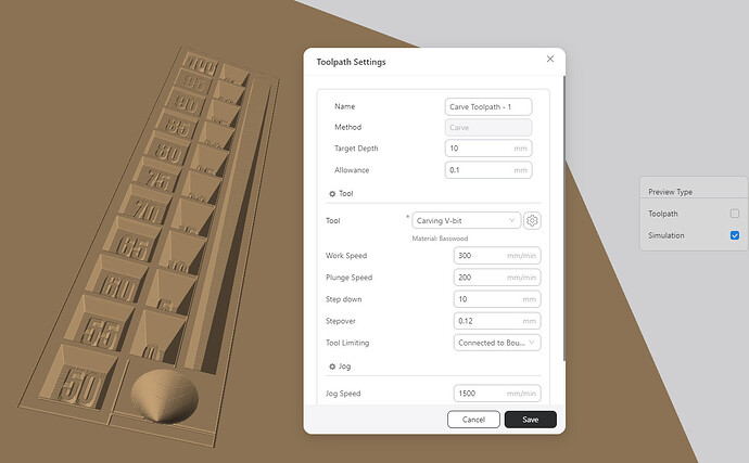
Simulated, I always put a small allowance so the Luban software will present it correct but it looks like with the latest version it may not be needed. Luban 4.12 renders things much better it seems:

Hopefully this helps you out…

1 Like

Using SVG seems to have done what I was expecting.

I ended up using five layers instead of three because of wanting some of the paths to be treated as filled (the screw holes) and others to be just cut (everything else), and also to ensure that the outline is cut in the last path after everything else is done, including the full-depth holes.

What remains is figuring out the tool speed. I’ve looked at Snapmaker’s recommendations for speed, but unfortunately, they’re based on using the larger 3.2mm bit, which won’t work for my purposes, because the screw holes have to be pretty much exactly 3.2mm with really tight tolerances, so I’m going to need to use the 1.5mm bit.

How does the bit size affect work speed, plunge speed, stepover, and stepdown? What I was thinking is that the official numbers are probably more conservative than they would need to be when using a smaller bit, because it is removing way less material, and thus would have way less torque on the linear modules, but that’s just guessing.

Based on that theory, I was thinking about the following settings:

Work speed: 300mm/min (100mm for the screw holes)
Plunge speed: 50mm/min
Stepdown: 0.2mm
Stepover: 0.5mm

Does that sound too aggressive? Too conservative? I’d love to go considerably faster, because I’m not looking forward to it running continuously for almost two days (though it definitely beats two months). I have no idea how I’ll be able to monitor it to make sure a bit doesn’t break. I can’t exactly stay in there with it constantly watching for 42 hours and 6 minutes.

I’m assuming that I should start somewhere in that neighborhood and then adjust the speed up on the touchscreen up to the point where the CNC module starts to slow down and then back off slightly. Is that a reasonable approach?

The final result has to be horizontally accurate to within a fraction of a mm, because it involves mounts for a motor and rotary encoder whose gears have to mesh with another gear, and the teeth are only about 1 mm long.

In plastic, if the mount holes were too far apart by even 0.25mm, the flexing would be enough to make the part fail. Aluminum shouldn’t be quite that intolerant of error, but the tolerances are tight enough to make Gimp and MS Paint are non-starters.

That’s why I started with 3D-printed models. Not including reprints because of printing issues, It took eight tries to get the alignment close enough for the gears to mesh reliably.

I basically did the equivalent of that, though, by doing a flat projection in OpenSCAD and exporting slices as SVG graphics. I then deleted chunks of the SVG slices and edited the fill colors to get the right results.

Same idea, different implementation.

Turns out I was being way too conservative, and stopped it pretty quickly and reworked it. I actually changed the stepdown to 0.4, and that seems to be working fine, but the 50mm plunge speed, combined with the 10mm jog height, turned out to be excruciating, with the machine basically spending 90% of its time doing nothing.

So now that I realize that it is going to apply the plunge speed even while massively above the origin (which I wasn’t expecting), I reduced the jog height to 2mm and increased the plunge speed to 100mm/min.

One other mistake I made was trying to eyeball the Z height. As soon as I told it to trace the work area, I realized my mistake, because the bit snapped. Fortunately, I had just bought a bunch of extra 1.5mm bits, so I was able to restart without waiting a week.

On the retry, I lowered it onto the spacer card for the 3D printing function until it was snug, then raised it by the smallest step possible, pulled out the card, and called that good. The first pass misses on a couple of spots, so I guess the bed isn’t quite perfectly level, but as long as everything is consistently off in the same direction, it should still be okay.

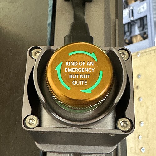
And a third mistake I made was mounting the emergency stop button in the center on the front, rather than off to the side. I, of course, hit the thing accidentally, and bizarrely, there’s no way to resume after that. I really don’t understand why you can shut the power off, and it will be able to know the state it was in and resume, but if you hit the emergency stop button accidentally, it won’t let you try to resume. It’s an arbitrary and glaringly wrong UI design decision.

It’s not like the emergency stop shoves something into a saw blade and breaks off teeth, where you would have to repair the machine afterwards. There’s really no good reason not to have it ask if you want to resume when you power it back on, just like it would if you had accidentally tripped over the power cord. :upside_down_face:

Anyway, it seems to be working. And now that I’m not plunging really, really slowly for 10mm after every tiny little cut for the screw head holes, it is only going to take 14 hours instead of 3 days. That’s much more survivable. :joy:

On all the emergency stop we have at the factory, there isn’t one that must be reset by power off. All have a reset button on the SCADA screen or physical a button to reset. Why SnapMaker makes it this way, I don’t know.

There’s a reason one hits the emergency stop, I’ve had to several times, and have NEVER found the need to resume (as something has gone terribly wrong). I pretty much always have to reset/scrap the work. Power cycling is somewhat inconvenient, but there’s a reason for it, so one doesn’t “resume” into an unsafe operation.

If you feel the need to resume a job, you probably could have just used the Pause button.

There are two reasons one hits the emergency stop. One is because something is horribly wrong. The other is because it is mounted at the edge of the enclosure, and when your enclosure is on the floor and you’re leaning over the machine, it’s really easy to accidentally brush it with your arm and trigger it.

If the pause button were mounted on top of the enclosure where it could easily get bumped accidentally, I probably would have. :grin:

So, can’t the emergency stop button be mapped as a pause button by some clever firmware dabbler?

Cool, and understood on the gimp or paint tolerance issues.

In your enclosure are you using the internal location for the touchscreen, where the hole is on the short side door? Using the nuts that slide in the channel, like for the emergency button, you can mount the original back-slanted touchscreen holder to the top corner where the doors open/close at. The back slant makes it vertical when attached to the enclosure frame rails and the cable will pass between the panel of the long side door and enclosure without making too much gap. You could cut a small U on the top edge of the door panel for the cable to pass, lessening the gap further if needed.

You can print a cover for the original door hole using the attached file, not my design it is from thingiverse linked below. It works well.

SM_Enclosure_Door_Panel_whithout_handle.stl (128.0 KB)

Snapmaker Enclosure Cover Panel by blackstyles - Thingiverse

At the factory, we operate 10 bridges over a channel from one location. The channel is 30km long. We hit the emergency stop in multiple reasons. A car that ignore the traffic lights and stay under the barrier. People that cross the bridge while the barrier is closing or the bridge is starting up. After that the situation is safe, we hit the Reset button to resume the service. If we must go local to reset with a power cycling, then the traffic is at least half an hour disturbed.

With the SM Lightburn, Deskproto, Octop(r)i(nt), … loose there connection on power down. Not a normal situation by hitting the emergency stop. Normal the SM need to send ‘Emergency stop used’.

LOL. Poor analogy. But A for effort.

I guess you never heard of Sawstop, etc. In emergency they basically destroy themselves to save the user. This is very clever and akin to a automatic smart Emergency Stop button. Emergency requires corrective action and start over, there’s no “resuming” from an emergency.

But I guess your definition of “emergency” is different than mine and Websters.

PA, maybe Snapmaker could add another button…