Gaps in certain spots

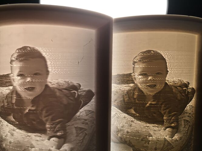
Hi there. I printed some Lithophanes recently and discovered some issues in the print. After reading, that it could be the Filament (SM white), that might be not the best, i ordered new Filament from a different brand (geetech) and i printed the same Lithophane again. And there the issues/gaps appeared at the same spot like before.

I used the Lithohanemaker.com website and the normal Lubansettings. But for me i just wondering, why the issues appears always at the same spots? Rest of the print is ok, also the bed leveling is pretty good.

@zwecke

I would say this may a layer width issue. Printing very thin or small feature on Snapmaker machine may be a challenge.

You can increase the wall thickness value in Snapmaker Luban Profiles.

As the layer is very thin, you need to slow the infill speed to 30mm/s to 50mm/s.

Ok, i already did those fine tuning in the settings.

It is still the question, why does it appear exactly on the same spot position?

In my opinion that looks like an artifact relating to linear advance. Before a print starts you could try issuing a M900 K0.07 from the terminal to temporarily change the linear advance setting to something that works for many people.

If that works, M500 to save to memory.

Hi thanks,

what does that M900 K0.07 means/make to the machine?

Sets a self destruct timer. I wish, ha.

You can read the docs here:

M503 will report the saved M900 value from EEPROM, which will be K0.22 if you haven’t changed it. In my opinion that is way too high for a short direct drive extruder like the Snapmaker has.

This really is only a plausible explanation if this area is at the end of the line, not the start:
image

A linear advance K factor that is too high will result if pushing extra filament out at the start of a line, and then retracting at the end, leading to drastic under-extrusion as the head decelerates.

Linear advance is designed to pressure-compensate for the springy-ness of filament in the extruder drive system, but setting it wrong has bad effects. 0.22, like comes from the factory, may be more appropriate for a short Bowden tube style extruder. 0.22 is actually the Marlin default, and has not been changed by the developers.

It’s a mystery to me why some people have issues related to this, and others don’t - could be the speed at which people choose to print - slower speeds will not exhibit the negative effects of linear advance as much as the acceleration is much smaller.

Is there an effective lower limit for line thickness and layer height? I’ve seen many general recommendations based on nozzle size and so forth, but if the Snapmaker has a minimum value for these it would be good to know it.

Line widths under 120% of the nozzle diameter will result in a malformed extrusion that differs from the slicer’s internally modelled obround shape, resulting in unpredictable fill and layer adhesion.

1 Like

So that means for a 0.4mm nozzle:

  • layer height <= 0.32 (80% of nozzle dia)
  • line width >= 0.48mm (120% of nozzle dia)
  • wall/shell thickness >= 0.8mm (>= 0.48mm, multiple of nozzle dia)

I guess we can assume the Snapmaker can handle all these numbers, shipping as it does with the 0.4mm nozzle.

How about a 0.2mm nozzle?

  • layer height <= 0.16mm
  • line width >= 0.24mm
  • wall/shell thickness >= 0.4mm (>= 0.24mm, multiple of nozzle dia)

I have in my notes that the Snapmaker has a minimum layer height of 0.05mm, and the stepper motors move 0.04mm per step, so that possible layer heights for the 0.4mm nozzle are 0.08, 0.12, 0.16, 0.20, 0.24, 0.28, and 0.32mm. So I guess the limits I am after are those layer heights, and the 120%-of-nozzle-diameter line width.

To sum up:

Layer height

  • multiple of stepper motor step (0.04mm)
  • > than 0.05mm (SM minimum)
  • <= 0.85% of nozzle diameter

Line width

  • >= 120% of nozzle diameter

Wall/Shell Thickness

  • >= line width
  • multiple of nozzle diameter

The first half of your post I agree with the numbers.

That must be a typo, 0.5 should be 0.05?

And I agree with the summary at the bottom.

The 0.04mm/step magic number is also accurate when considering only full steps, and I have printed with Z heights that are not an integer multiple of that number and had good luck. The microstepping is smooth enough that it’s not strictly important to me. I’ve printed at a 0.15mm layer height just fine. The issue with the magic number is mostly important to not lose steps by commanding a smaller movement than can be executed. As little motion as 0.015mm will result in movement, so I’d wager the practical magic number is somewhere around there, maybe 0.02mm, especially if backlash compensation is enabled.

The actual minimum step in software is 0.0025mm, so practically the machine is not going to lose any steps while traversing in Z, and on average any subtle variations should smooth out.

While a movement command of 0.0025mm will not actually result in any motion, once in motion the machine can achieve quite good repeatability, much better than 0.04mm.

https://support.snapmaker.com/hc/en-us/articles/360046836553-What-are-the-repeatability-max-travel-length-and-backlash-of-the-linear-modules-of-Snapmaker-2-0-

1 Like

Yes sorry, that is a typo. Will update.

Hi guys,

thanks for all the input, but for me it was hard to follow and understand, because my technical english isnt the best. So far, i didnt get all the information about the numbers with height, width and thickness - sounds interesting but i dont understand it fully.

I tried a new print with and changed the linear advance setting to K0.07. But it is the same result, the same artifacts at the same spot. :frowning:
I have no clue or technical understanding what is physically happening there - i cant imagine why always at the same spot - even if i turn the print 180° and set it on a different position on the bed.

Does that Lithophane page suggest to change some specific slicer settings? It should do it somewhere.

That’s good to know - thanks for trying the linear advance change, but it’s clear now it’s not that.

Would you mind posting the gcode file that Luban generates? You may have to zip it into a .zip file.

Nope. It just create the stl-file that i load int o my slicer, in my case Luban.

Hi, generated the gcode with Luban. The gcode is to big in size even as zip.file.

Sorry :frowning:

Sorry, yea meant Luban. Google Drive or Dropbox? It’s basically impossible to troubleshoot an obscure print issue without being able to see what the machine is being commanded to do.

Thanks for PMing me the gcode. Here’s my analysis, with follow along steps as requested.

First, load into gcode into ncviewer and orient the image, adding G21 and removing the header so it renders properly.

You have issues here:
image

Looks a lot like the gcode here:
image

Now why would that be?

Zoom in and play back that section line by line

There is a front wall, a rear wall, and then a bunch of tiny little segments inside the wall because the wall is too narrow to fill with a continuous string of filament.

So the gcode is commanding the machine to lay down intermittent short segments as fill. This is a terrible strategy and will fail easily, due to stringing or poor adhesion.

Your print temp is only 197, which unless you’ve optimized already seems too low.

My theory is the filament is not adhering properly to the below layer, and being pulled up into a ball by the internal shear forces.

However, this is a very thin wall, so if you raise the temp too much it will sag if there’s not enough cooling, something the original head design struggles with.

Printing this successfully may be out of the realm of this machine without additional cooling, or tweaking.

I don’t think Luban (Cura, under the hood) is slicing this intelligently. Simplify3D (and I believe PursaSlicer also) has a variable width extrusion to fill thin gaps that would be ideal here. The interrupted extrusion is not likely to work here unless you fine tune everything such that there is no over or underextrusion at all, and it has to be perfect because it’s at the top of the model.

Another option to try would be to increase or decrease the thickness of the model wall, or the extrusion width in the slicer, so that the slicer does not generate interrupted segments.

You’ll need to carefully preview in Cura or S3D, as the preview in Luban is not useful for this level of detailed troubleshooting. After the previews look good, then I would do a special slice where only that problematic section is printed, to save filament. Once a proof print of that section works, only then I would again try the whole print.

Again, this is a challenging print for this printer. You may want to revisit the whole slew of calibrations at Teaching Tech, and recalibrate e steps and flow at the minimum, otherwise it will be very difficult to get this to print correctly. A temp tower might also be a good idea if you haven’t already done so.

Can i do this? What is a ncviewer? Can u recommend one? I would like to see this blue/orange picture as well to get more into it… And also the zoom to see the travel of the extruder would be interesting to see - what do i have to do to get these?

I print at 197°C because the SM Filament says its printing temp is 190-210°C.

Where are the settings for the extrusion width in Luban?

The test vase is also a very thin wall, and this was printed perfect. Maybe because there were no gaps to be filled?

I would like to know much more about that detailed workflow to understand the machine and its behavior in detail.

Thanks so much for ur effort and patience!!!

https://ncviewer.com/

It sounds like the recommendations are: