Hi there,
well i think i can’t get my head around a problem i have. I bought a Nankuk 915 hard case. Now i would like to cnc a cover that fits inside it, matching the inlay. Bought a plastic sheet with 3mm that has the exact length and width that is needed except the corners. The Radius needs to be 55,7882mm. Since the length of the case is longer then my A350 can handle i have to cut it in multiple passes. My idea is now to prepare the cnc to just cut one corner at a time. What do i need to draw in fusion that i will only cut my outer radius and not ending up with a triangle that has a rounded corner. Do you know what i mean?? ![]() Please help…
Please help…
Thx in advance
Ralf

Make a box with one corner with the radius you want.
Create a sketch and draw a rectangle that just goes along the sides but not all the way to the other corners.

Create a setup and set your stock size to relative size with zero additional.
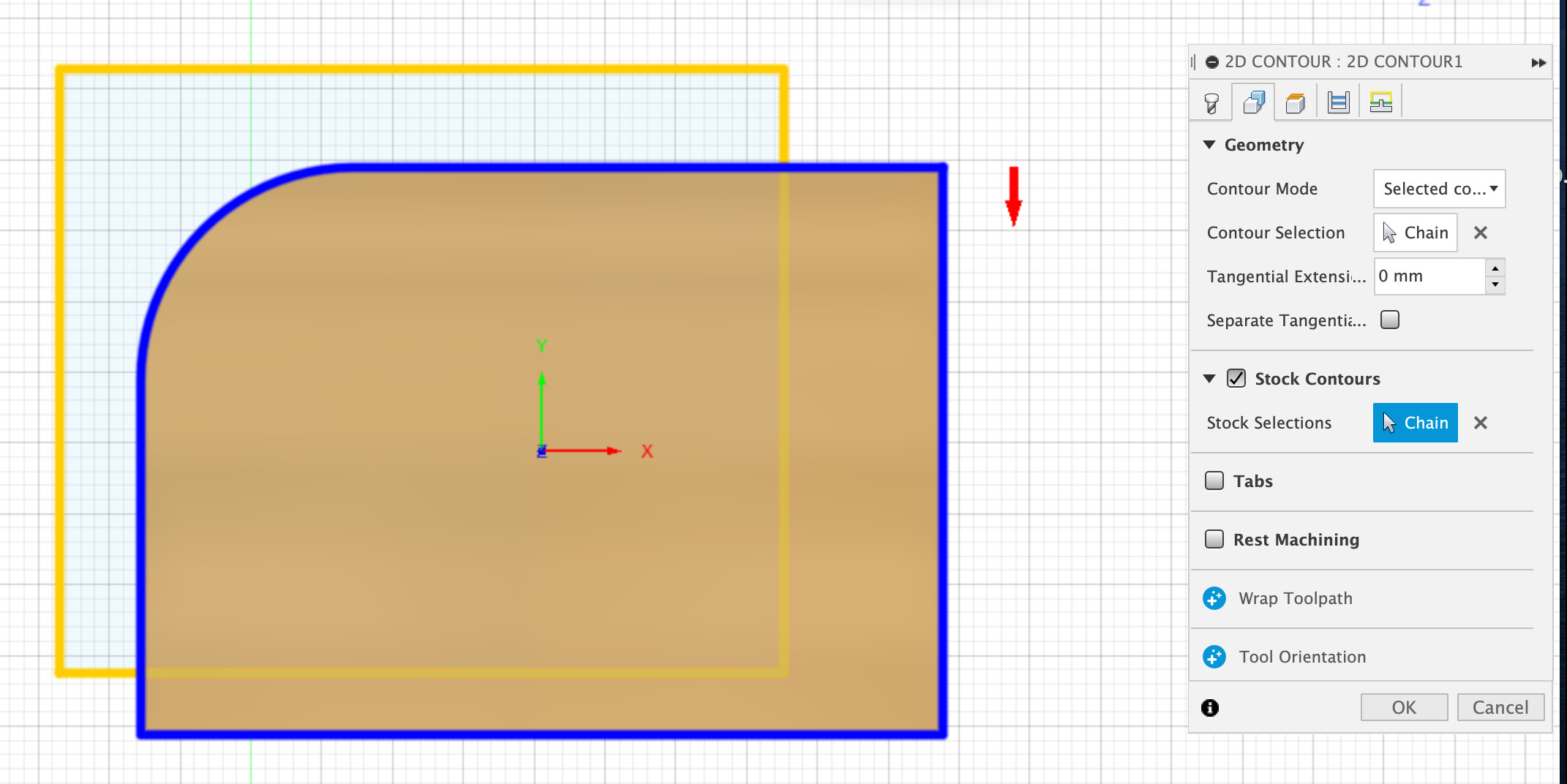
Select the contour of your shape under ‘geometry’. Select the sketch rectangle under ‘stock contours’ (this is what limits the area of what is cut)
Make sure you set appropriate settings for speed and multiple stepdowns for your material.
As far a lining things up you’ll have to do some math and measuring.
Or just start wide and do a pass and slowly move your work origin in until it’s where you want.
Once you do the first one you can either clamp some extra wood down to line up the last 3 or if not too picky trace the edges with a pencil.
-S
You are a legend! Thx heaps for that. Will try it and let you know.
Cheers
Ralf
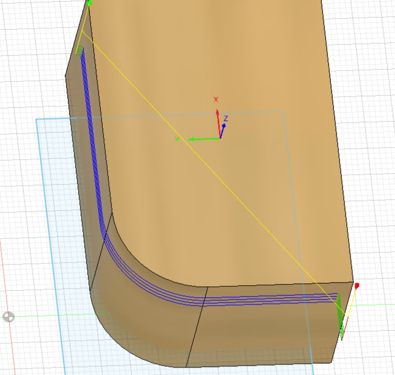
It seems I am doing something wrong. It always cuts the inside of my rounded corner during simulation. Sorry I am a noob when it comes to Fusion360. This is what I do. I design my rounded corner, then I extrude it. Create a rectangle and that is going to be my boarder. Switching to manufacturing, create a new setup, set it to relative size box and Stock Offset Mode to No additional Stock. Select under 2D, 2D Contour. Select my tool and under Geometry Contour Mode is set to Selected Contour, selecting the rounded corner bottom and top one. Under Stock Contours i select my rectangle. Set multiple heights etc…
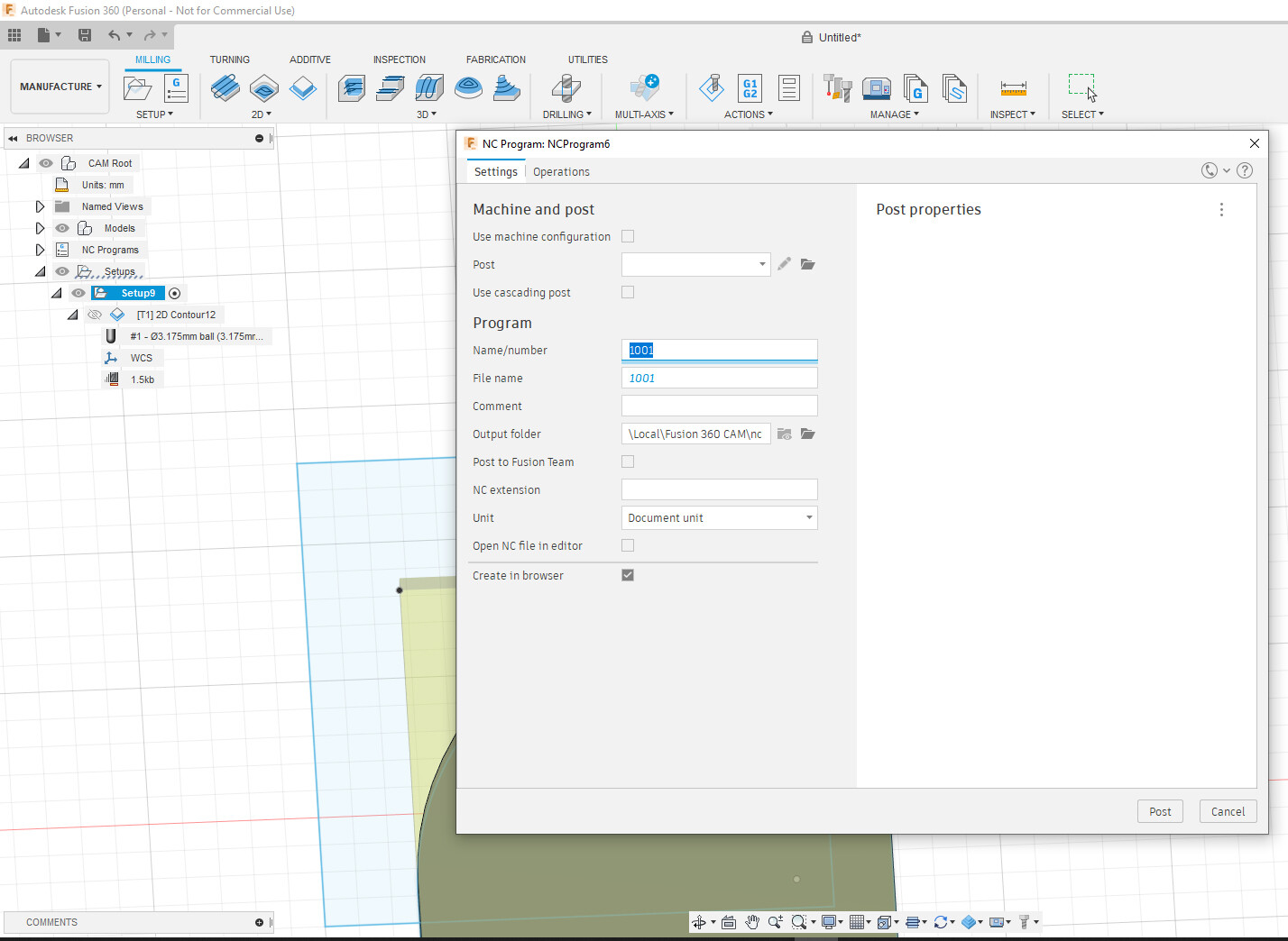
Also what to do on Post Process, because i am confused. I followed this tutorial:

The window that pops up ist totally different… ![]()
Any idea?
Consider watching some more detailed tutorials. It looks like you’ve selected the wrong face to apply the toolpath to.
Something like this: How to Get Started with CAM Within Fusion 360 | Autodesk University
and this: Fusion 360 CAM Basics - YouTube
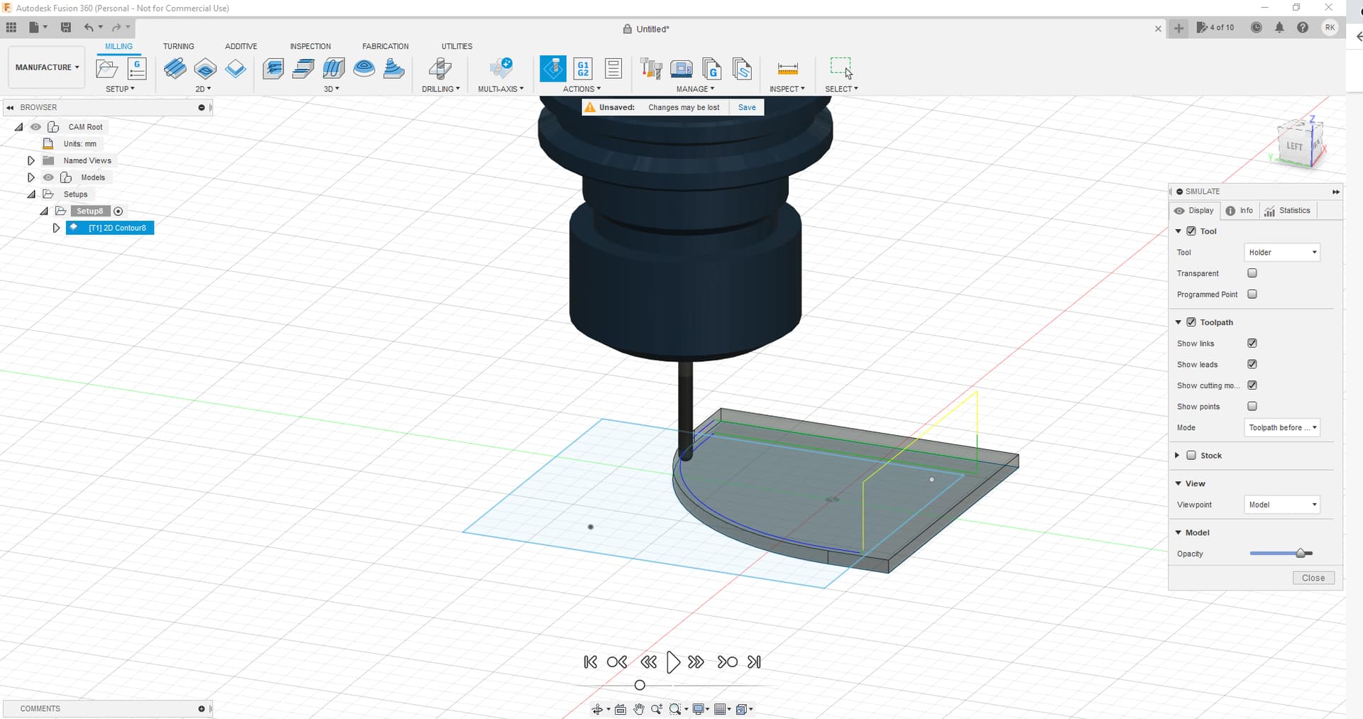
It seems like i got the Problem figured out so far, when simulating it seems it does what I need. However, the Post Process Window is giving me grief now. Any idea, why its causing it? I did install the snapmaker fusion files…
Cheers
Ralf
I found a snapmaker.cps file, when loading this file it outputs me a cnc file. Will try it and see how it goes… wish me luck, oh and i am watching these tutorials as well.
thx
Ralf
Sounds like you were selecting the top and bottom contours?
You only need to select one. Doesn’t matter which one - just will make a difference in how you set your heights. If you select both it will think you want to only do between the two selections which since they’re identical confuses it.
Definitely need to have the SM config loaded but that will only make a difference for post processing and creating the gcode (maybe simulation?).
-S
Last question on this topic I promise ![]() It seems everything is ready for cutting. The 0/0/0 Point in Fusion is that the Origin Point i have to align to on the snapmaker?
It seems everything is ready for cutting. The 0/0/0 Point in Fusion is that the Origin Point i have to align to on the snapmaker?
Thx
Ralf
Depends on how you’ve set it in setup in Fusion. Generally the default is top and center of the object.
But for something like this you might find it easier to set it to top and upper left.
Always run boundary well above workpiece and any clamps/fixtures before starting a job.
If things look good after that you can also start a job with z-origin set 1mm or more above the stock and start it to see what the actual path is doing (since run boundary just does a square of the outer limits) without it actually cutting anything.
-S
Is there a way to make the origin visible? When i hit the eye symbol in design mode, i see the y and x axis highlighted. I did a test run with my SM and set the origin exactly to the point that is shown in Fusion, but it seems, its way off. Could it be that this is not the orign for my machine. I did find the settings for the WCS, could this be the origin for my cnc machine? ![]()
thx
Ralf
Under setup is where you select and see the origin.
I believe there are also settings when you run a simulation that will show it. Haven’t run a simulation for a long time so don’t totally remember.
-S