A good pickup that the carriage holes are not true. It should be fairly easy to fix like the DIY cylinder head procedures, say a sheet of glass with 320 grit sand paper glued on and then use wd40 as a lubricant and you should be able to true up the holes. What do others think?
@Tigercjn I think we shouldn’t have to true up holes on a $1500 machine.  but if you wanted to that would probably work.
At this point I just want the thing to work, any means necessary. I like the idea of trueing the holes, but I’m concerned it’s so out of true that I’d have to sand off nearly a full millimeter of metal to get all the pads to touch the plate at the same time. By then, surely I’d grind it at an angle and it’d be planar, but not trammed.
I have a boatload of these:
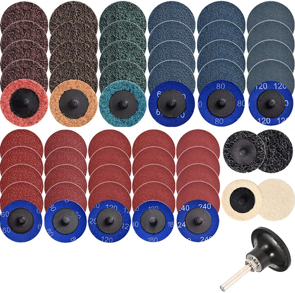
Considering chucking that in the CNC spindle…
Sounds like a good plan as long as your assembly is tight
I’m way out of my element here (3d printing n00b, never used laser or CNC), but I was starting to wonder while reading this thread if it would be possible to level it off with the CNC similar to the way you would a level a wasteboard. Nice to see I may not be completely crazy in that regard. 
If you do this, and it works, I’m sure a lot of people who are having issues with bed leveling would be interested to hear about your process and results.
Keep in mind he is talking about using a sanding bit to slowly sand just the screw holes… milling aluminum is a completely different topic… and I doubt the A350 has the redgidity to actually mill aluminum.
Be careful that you don’t end up chasing your tail down to nothing.
Not to pour oil on the fire so to speak Brent but I was wondering whether you have a small engineering works near to you, that you could ask to true up the pieces on a surface grinder. Possibly someplace like a garage that rebuilds engines and would be familiar with taking a small skim off an engine cylinder block. It’s not the amount of metal you have to take off, it’s just being able to take it off perpendicular and parallel to the base.
You can tell me to shut up if you want. :)))
@jepho we talked about taking it to a machine shop that has a large enough mill, but we want answers from Snapmaker before we get too far into modifying permanently. Still awaiting support response from the inquiry made in conjunction with this post 
Yea, I want to hear what the design tolerance for this part is. I feel that a deviation of +/-0.08mm on a flat and +/-1mm corner to corner is too much, but maybe that’s within spec.
And no machining or sanding until I can afford to break it, and that will be after I have a spare on the shelf!
@ITmaze, definitely agree you can’t chase impossible perfection. To start I want to identify is my part defective, or “meets spec”. If it’s defective, then a replacement is in order and that’s that. I asked support what measurements need to be taken to conclude if this meets spec or not, so far, crickets.
If it’s not out of spec, there are avenues… like machining. @jepho machining this looks expensive - fixturing it on the intended mounts doesn’t look trivial. Definitely not as easy as clamping in a vice on some parallels. Almost looks like a custom fixture with mounting screws will be required.
Good luck with getting support to answer you in any meaningful manner. I wont be holding my breath. 
Yes Brent, it is not as cheap as having the original part working properly in the first place, I grant you. I was just considering how it could be made to perform its job within an acceptable degree of tolerances. Frustrating as hell… I recently purchased a pillar drill and the column was not at right angles to the base! It was no use as far as I was concerned because the only purpose to a pillar drill is to drill holes that are perpendicular to the base.
It certainly appears as if team Snapmaker have taken their eye off of the manufacturing ball. I do hope they get it sorted for you. A new machine that falls well within the expected specifications would be a good start.
Certainly could mill aluminum with proper endmills coated so you can run end mills dry.
Only in the center of the bed though as you move out the bed is too flexible. I have a poorly made base it took a 0.020 aluminum shim between the base and MDF and it is reasonably flat now. I think milling the MDF to get closer to perfection would work well. I have cut 15 parts cut positioned dead center on the base 7" x 2" Black Walnut mostly, and the stability and repeatability is excellent, definitely can’t take big cuts but the machine is very repeatable and accurate within its limits. It is hard to tell the cuts were not done on a mill. The fact there is nearly no backlash is a excellent feature of the A350. I think the aluminum base is a bit flimsy for the machine size though, A350. If someone made a kit to replace the base with a heavy duty version of the base and spread the Y AXIS apart the rigidity of the machine would be awesome and with a more powerful spindle would be able to tackle aluminum. Probably should have some covers to keep the axis insides safe from swarf. This would make the machine very rigid for the size of the large work area. Also throw out your warranty.
Just thought I’d share a picture of how I tram X now. This is fast and precise to do before I turn the machine on and home.

Yesterday I deliberately left it 0.01mm low on the close side, and I could easily slide the far block under X, but the close side was too tight and the block hit the side. On the touchscreen I raised the Z height by 0.1mm and was easily able to slide both blocks in. Not making any claims on exactly how precise this is, as I’m aware of a slight rotation in the Y modules relative to X. But, this can quickly get to better than .1mm, and likely better than that.
Clever …123 blocks in case some are not familiar.
From: snapmaker@discoursemail.com
Sent: October 22, 2020 7:46 PM
To: Ron@jfgsystems.com
Reply-to: snapmaker+c283094d6d7da8e9246eb344da811a86@discoursemail.com
Subject: [Snapmaker: where creation happens] [Snapmaker 2.0] Carriage Tolerances - Unusable Over Distance >75mm From Center
|
- |
| brent113
October 23 |
- | - |
Just thought I’d share a picture of how I tram X now. This is fast and precise to do before I turn the machine on and home.
Yesterday I deliberately left it 0.01mm low on the close side, and I could easily slide the far block under X, but the close side was too tight and the block hit the side. On the touchscreen I raised the Z height by 0.1mm and was easily able to slide both blocks in. Not making any claims on exactly how precise this is, as I’m aware of a slight rotation in the Y modules relative to X. But, this can quickly get to better than .1mm, and likely better than that.
I agree it should not be necessary, but my machine has been on a holiday since shipping from the factory around 40 days ago, it’s had a lovely trip on the ship and has now disembarked in Sydney.
I live in Melbourne so I think it will now take a trip on a truck and I hopefully will arrive next week, I want to take my time and check and adjust anything as required to get it running the best I can.
Hopefully it was shipped prior to the rail problem, just hoping that I won’t have any problems.
Cheers
Chris
That may be a good idea to use the CNC chuck to polish/sand the bolt holes true.
Based on that I should have mine around Australia Day 
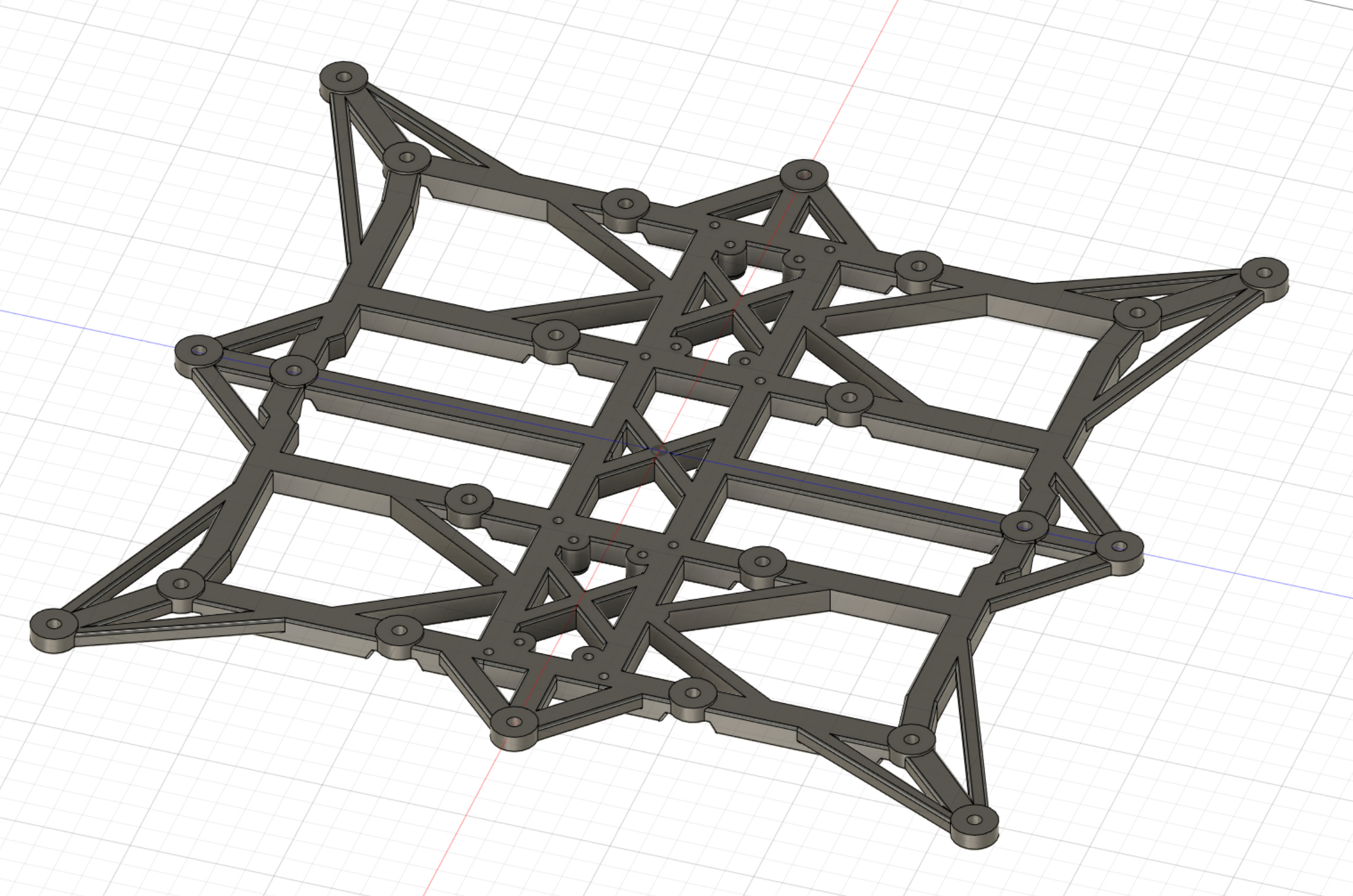
With all that frustration with bumping of linear modules and tolerance, I decided to CNC a new frame(mounting platform). I want to make shim parts with a bigger radius, it could help with flatness of mounting «beds». 16mm vs original 10mm.
I also want to make more connection points between frame and linear modules for vibration damping between them, so I added a few holes to design.
So i hope with a new frame and new linear module i can reach better results with my A350. Or not. I start thinking that it’s not possible to get good results with that machine.

Making new mounting platform seems like a great way to enhance the performance of the machine without altering any of the original parts that would void the warranty.
I’m not sure how important the weight of the frame is to the performance of the machine. It seems like more mass would result in more load on the motors, increased backlash, wear on the drive screws, etc, so using a solid plate of aluminum might be bad. What about carbon fiber though? I’ve been wondering if a thick sheet of CF could be inset with the necessary threaded inserts to create a lighter, flatter and more rigid mounting platform.