Achieving a good first layer A350

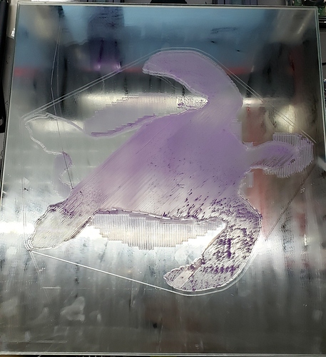
Another $70 spent on my bed level issue and this is my result. Got two 1/4" mirrors custom cut which are flat by nature or the reflection would be distorted. Ran a 5x5 auto level while bed was hot and here is the resultant print. I stopped it before it finished the 1st layer since there was no point in continuing with the 17 hour print. 0.2mm 1st layer at 15mm/s and 1.1 flow.


I bought the A350 so I could print big but it seems that is not in the cards for my machine.

Yeah Creality

Hey, why didn’t you run a 5x5 calibration (after firmware update) ?

Actually I did run 5x5 on the metal frame and then adjusted Z for glass 4mm, if anything was worse than manual 3x3. I know the glass is flat, problem seems to be the delta between highest and lowest point and how that is averaged out across the mesh.

How are you calibrating for glass?

I have a steel sheet that I lay on the glass bed and allow the machine run it’s routine. When it moves to center for the Z offset, I remove the steel plate and zero to the glass surface. Even with all of that I still have a 0.5 - 0.6mm variation between min and max probe points.

Thanks did the same thing but used the naked bed surface, didn’t notice the sensor stopping over any of the screw holes so should be fine, then slipped the glass under for final Z offset.

The variation I think is just too much.

Yes I agree. There is not enough Z resolution to create a smooth transition plus the added error from the inherent backlash compounds the issue.

When using the calibration tool, I was surprised on the readings. Let’s say the calibration tool reading is -0.2 e.g. we’ve pushed down into the bed. A retraction of 0.1mm will not result in -0.1mm but more likely -0.16mm ? :man_shrugging:

So I’m back, @Edwin reached out and asked me to check a few things, carriages seemed flat with no wiggle.

So I started with more probe tests, first of all removing the heated bed itself:

Number in brackets is the mm on the probe, other is Z as shown on the machine co-ordinates on panel.
So my minimum step is 0.1mm

 0        1       2

0 6.10 (0.02) 5.90 (0.07) 5.70 (0.10)

1 6.10 (0.02) 5.90 (0.03) 5.70 (0.10)

2 6.10 (0.10) 6.00 (0.01) 5.70 (0.05)

Delta: 2,2 - 0,0 = ~0.40mm which is better than before.

I decided to check every bolt again and then noticed the underside of the platform that I’ve never touched, turns out some of the nuts were a little loose. So tightened them all up.

After checking every bolt again (and nuts underside of platform)
Glass on top of platform, using probe.

 0       1        2

0 5.97 (0.01) 5.97 (0.02) 5.97 (0.01)

1 6.07 (0.00) 5.97 (0.01) 5.87 (0.00)

2 6.17 (0.03) 6.07 (0.00) 5.87 (0.00)

Delta: 2,2 - 0,0 = ~0.10mm

Next, putting the heated bed back on and checking the bed itself (not using glass)

Heated bed (19C room temperature), using probe.

  0       1       2

0 5.10 (0.01) 5.20 (0.01) 5.20 (0.02)

1 5.20 (0.03) 5.10 (0.05) 5.10 (0.00)

2 5.20 (0.00) 5.00 (0.04) 4.90 (0.01)

Delta: 2,2 - 0,0 = ~0.20mm

Time to put the Glass bed on and test with probe.

Glass on Heated bed (~60C), using probe.

 0        1       2

0 9.10 (0.01) 9.10 (0.05) 9.10 (0.04)

1 9.10 (0.05) 9.10 (0.02) 9.00 (0.05)

2 9.20 (0.02) 9.10 (0.06) 9.00 (0.04)

Delta: 2,2 - 0,0 = ~0.10mm which is good. As this had been ~0.60 previously!!

In general, this is nice, very little variance. So I would hope will give a good 1st layer as little for the mesh matrix to do.

Next steps, time to print out some first layer test squares.

Next steps, did a manual 3 x 3 calibration. Sorry I don’t have M420 V to show as it doesn’t over WiFI.

Back to printing the auto spool rewinder I’ve tried to print previously:
STL: AutoRewind Spool Holder for SnapMaker A350

Settings: 0.16 mm Layer Height
1st Layer Height: 125%
Print Speed: 50 mm/s
PLA 210/60

Success, much better than previous attempts.

13 hours later…

It really feels like I’m now using A350 for the first time! So triple check all your bolts and also check the nuts on the underside of the platform.
11 Likes

May you could probe print-sheet vs glass again for us please? Thanks in advantage!
Be sure to recognise your settings first (M503 or M420V) to easily get back if needed.

EDIT: M503

I thought about it, but wanted to enjoy it working for a bit :laughing:

I will try and do this soon, the problem I have is I can’t get the CH34x based serial USB to work in Mac OS so am limited with commands. WiFi doesn’t support M420V, is M500 supported?

I think when I looked at the firmware they use an API for WiFi vs some kind of Serial over WiFi connection which would provide the same experience as USB/Serial Terminal.

1 Like

No M503 and M420V doesn´t work over wifi…
EDIT: M503

So managed to get the USB <> Serial working, will post how in the other post. However, quick 420V of the current levelling, which surprised me.

M420V
others < Bilinear Leveling Grid:
others <       0      1      2
others <  0 +8.600 +8.450 +8.450
others <  1 +8.800 +8.750 +8.650
others <  2 +8.800 +8.850 +8.900
1 Like

Why are you surprised?

Was expecting a little less delta, after previous probe tests.

circling back, @xchrisd I put the magnetic bed sheet on and re-calibrated.

M420V
others < Bilinear Leveling Grid:
others < 0 1 2
others < 0 +6.009 +6.049 +6.130
others < 1 +6.447 +6.440 +6.404
others < 2 +6.499 +6.507 +6.610

Back to that large 0.6mm delta and 1st layer was poor. So I would say certainly in my case the magnetic print surface is not up to the required standards.

1 Like

@Dojima

Please put the print sheet on the heated bed and you can use a rule to check if the surface of it is uneven.
Place the ruler horizontally on the surface to see if there are any gaps

It will be appreciated if you can take a picture of it for me.

1 Like

@Dojima

Also PM you just now.

Best regards

I have the same 0.6mm delta between points.