Over/under-sized features on prints

Hey, it got features printing reliably :wink:

Yeah, been through the teaching tech site, and that didn’t exactly blow me away with the perfect (or even successful!) prints when I was done.

Been trying other methods. For example, I found it was actually faster to iterate through possible k-values for linear advance (less than an hour), once I knew the general range, than to attempt to get the K-value GCode to print successfully (an entire day, which ultimately ended in failure).

The last-mile, as it were, for calibration seems to be pretty dependent on, or perhaps limited to, filament and hot-end combinations. Those are going to change much more often than the slicer, so I’m not sure I see the problem with slicer-specific calibration. As for the specific information on that site, it is for a different printer and different slicer software, so of course it cannot be followed by Snapmaker users as a step-by-step guide. Like most information, glean what ya can from it to find your own repeatable solution.

I m going to buck received wisdom and note two things.

  1. Calibrating xyz esteps is as critical to dimensional accuracy as flow and extruder esteps. I note some say not to bother and flow or extruder esteps is as good, my testing shows me it isn’t, why? Because neither flow or extruder esteps affect xyz proportionally in all 3 cardinals. So calibrate extruded esteps, calibrate flow to make sure you get right flow on a flow cube (wall thickness). Then calibrate linear advance. Then calibrate xyz esteps and you should be easily able to get to 20mm xyz cube to within +/- 0.01 on your calipers and maybe better on a micrometer. (On a 120mm object mine prints within +/- 0.06)

  2. Holes on vertical surfaces never seem to be round (holes on horizontal surfaces are). No one has told me how to fix this on /r/fixmyprint. The general consensus there was holes on vertical surfaces get squished a little and it is an artifact of 3D printing in general. Esp for small holes. Using features like Prusa slicers detail mode to double layers (aka smaller layers) seems to help but not solve. Some will knee jerk claim you have zblob, maybe but if you have done all calibration and retraction and deretraction tests and calibration probably not. Only solution folks have given me is to cut small triangle shape in the top and bottom of the hole. I haven’t tried this and continue to look for other slicer based solutions.

I would love to be wrong on #2 and have some show me how to make perfectly round and correct size 2mm holes on a vertical surface :slight_smile:

Another neat set of STL files:
3D Printing Terminology Visual Displays
Haven’t tried these yet. Got the printer tied up doing a few of those torture tests now that I can get reliable output from it.

That was the reasoning that led me to create this thread originally. I had modelled an indicator clamp for the shaper toolslide to use in setups, in line with my intended use of the 3D printer to prototype pieces in plastic before wasting expensive metal. The pieces fit the dovetail (though not as well as I would have hoped), but I had holes in all three axes, and none of them were suitable for their intended use as through-holes for bolts, dowel pins, indicator stems, etc without drilling them out. In summary, every relevant measurement on that (and similar) parts was incorrect. I was worried about the ball-screw e-steps just as you have mentioned.

I’m convinced now that the guys were right, and that this was an extrusion problem. But how to fix it? The first step is to stop doing flow control in the slicer, and fix the firmware values instead. The relevant firmware values are e-steps and linear advance k-factor. The k-factor depends on e-steps, so getting that one right is key.

But back to the “horizontally-oriented holes are not accurate” point: this is exactly the same problem as bridging/overhang, just scaled down a bit. You can add internal supports (and trust me, those are NO fun to remove), or slow things down so the filament has a chance to set, and start messing with wall settings (the slicer should see the hole as a perimeter).

As for the xyz-esteps, the Snapmaker platform actually provides a good opportunity to test this. I used the laser to engrave a 20mm rule in 0.5mm increments that I generated programmtically in OpenSCAD. Now, the test wasn’t perfect, because Luban’s STL import required manual resizing of the object, but when the ruler is lined up on the Luban gridline and printed, the results are accurate. The same can be done in CNC, perhaps by milling tabs in aluminum a specified distance apart and then applying calipers. I haven’t tried the CNC function yet, but the laser experience convinced me that xyz esteps are, as @WilliamBosacker pointed out, not a significant source of error.

I was a bit brief in that update and certainly left out a lot of steps in my process. Those two projects are dedicated to the exact problem i was having: printing parts to size, whether that is mating-size (both mating parts are printed) or nominal-size. The models they provided, and the steps for getting those models to work, were a big help in getting my OpenSCAD models to print to the correct size. Bascially, those S-plugs are fantastic for debugging this sort of problem because a) they are small and quick, and b) the mating surfaces are quite demanding.

What I left out was that I made heavy use of Triffied Hunter’s Calibration Guide, with the 5mm calibration cubes model as well as the standard thin-wall model, to calibrate the e-steps more accurately (that is, through an iterative process, changing on-the-fly via the Luban console every 2 layers). Once the e-steps were producing good results, I used the k-factor reported by @brent113 in response to a different thread of mine, and iterated through 5 steps either side of that value in .01 (the smalled possible increment for k-value, as I determined by trying to set .005 increments) increments using a double-walled calibration cube for 6mm nozzles (did I mention I’'m using a 6mm nozzle? probably not). I verified the value with the Calibration Minimal Fish model, which came out excellent. I found the Prusa documentation on Linear Advance to be more helpful that the Marlin documentation, which simply treats the K-factor as a magic value and says “run this gcode and eyeball the results to determine the value”.

One thing to note: I am still getting horrible first layers. Between the bed being out-of-skew (as report elsewhere, there is a left-to-right difference of 0.32mm on the X axis, and a fore-to-aft difference of 0.12mm on the Y axis) and the build plate not longer being flat due to the force exerted in getting some welded PLA off it, that first layer varies between “Z too low” and “Z too high” over the about 30mm. But this is not relevant to the problem originally reported in this thread.

2 Likes

–Given the issues i just saw with calibration after setting xyz esteps i recommend no one do this until someone verifies if this or isn’t an issue–

As I indicated, I know I am going against received wisdom. :slight_smile:
I have seen articles say to use flow rate to control xyz dimensions - which makes no sense to me at all.
Resizing model for each axis individually totally makes sense to me.

I only did this to eliminate xyz tolerances from an issue I am having printing the 3 piece snapmaker quick change toolhead on thingiverse - i still need to try reprinting it after having now done all the recommended calibrations.

In terms of xyz tolerances I got to 20.00 +/- 0.01. The excel bellow shows the starting and end values. The only one of concern to me was the X value as .1 is large enough difference to affect that print. And yes one can have a good debate about whether its possible to measure to that accuracy with calipers, micrometers, given the PLA models surface bends while measuring, bumps caused around the edges of the XYZ letters on the cube, etc etc. But the amount of error here is trivial for almost all things i can think of doing. But is is worth checking that’s the case on any give machine IMO.

I have yet to reach my own conclusions. But this is a fun hole 3D printing has dropped me in :slight_smile:

and I am still interested to know if its possible to get a 3d printer to print a truly round 2mm hole on a vertical surface without mucking about with triangles cut outs (or supports inside the hole)

Thanks, that was super interesting.

At this point i think for small holes i have just accepted its an artefact of 3d printing as that what so many seem to be telling me. (if true, as a person new to all of this, i am a bit gobsmacked the slicers are unable to account for this and provide correction). As such I plan to create smaller holes than needed and drill them to round to compensate (yet to see if that really works). As that seems easier than using supports in them!

Oh and for folks following along at home, doing K value or xyz esteps invalidates the saved surfacce calibration mesh so make sure to recalibrate after doing that.

2mm is pushing it a bit. Most people would be hard-pressed to make a round 2mm hole with a drill :slight_smile:

1 Like

Lol, was more thinking about my larger holes, the 2mm ones are only air vents on the model i made so don’t really matter :slight_smile:

But for context this is the thread on /r/fixmyprint where I solicited feedback.

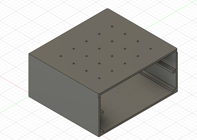
This is the original model i made (first time i had ever used a CAD app).

It was printed with the back surface you can’t see on the bed meaning those holes were vertical on the Y plane. I haven’t tried to see if X plane gives different results
 ? The holes ended up 1.8mm tall x 2.2mm wide - the box itself measured +/- 0.2 of a mm on any axis.

And given M92 doesn’t seem to survive power off / on (just saw the other thread) this would have been printed with default 400 value for xyz esteps.

1 Like

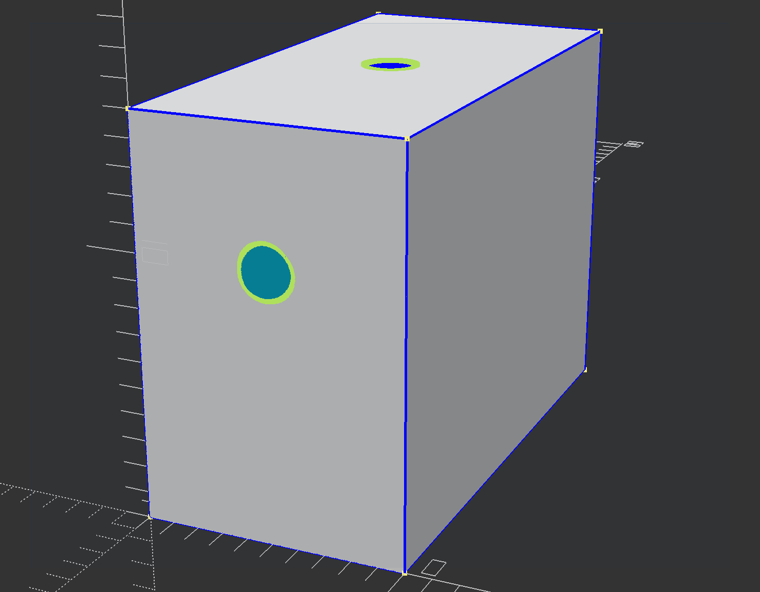
Too late! I modelled this in OpenSCAD to give it a go when the printer is free tomorrow:

line_width=0.4;
facets = (PI * 2) / line_width; //2mm dia

difference() {
    cube([10,20,15]);
    translate([5,10,0]) 
        cylinder(h=20, r=1, $fn=facets);
    rotate([90, 0, 0])
        translate([5,10,0])
            cylinder(h=20, r=1, $fn=facets);

};

I used circumference to estimate how many facets would be needed to make a hole “round” based on a given line width. Because an STL is just a bunch of triangles, this is not an unreasonable approximation.

To illustrate the problem:


a 1mm line size has embarassingly obvious facets.


an 0.4mm is much better


but an 0.04mm line width is phenomenal.

Now, the STL file is a triangular mesh that the slicer turns into gcode paths, and these paths are going to be doing what OpenSCAD is doing here: creating facets to approximate a round hole. With horizontally-oriented holes, this would indicate that layer height and line width should be the same value (or that width should be a close multiple of height; extrusion gets weird). With vertically-oriented holes, you only have to worry about line width, and it just has to be small enough for the number of facets (in Y usually) to be large.

2 Likes

That 2mm-hole print turned out to be a pretty good test (well, once I fixed the errors in the OpenSCAD code).

The horizontal hole printed out spot-on at 2mm, but was not quite round. The vertical hole was very round, but only 1mm - I’m guessing that was a perimeter wall setting having the minimum number of walls too high.

Did enough printing yesterday that heat creep killed the print after this one (and may have been responsible for the extrusion errors that mesed up the 2mm hole)


1 Like

Last night I modeled some replacement motor brush caps in OpenSCAD. These are for the motor of a Cincinnati toolpost grinder that came with my lathe, and the bakelite or whatever they used was so brittle that one cracked when I unscrewed it. Of course it is an uncommon size: I found one and only one vendor who will provide them, twenty bucks a pop, minimum order of ten. Total failure of capitalism to reallocate my money.

To return to the point, printed these overnight and they are just about spot on, The large diameter differs from the original by 0.02mm, which I think I would call in-spec. The screwdriver slot is under-sized (0.056" instead of 0.62"), and that appears to be due to a small amount of bulging from the wall (I had set wall width to 0.375mm and layer height to 0.08mm, hoping to get crisp threads). The threads are too shallow, which doesn’t bother me much as they didn’t look right in OpenSCAD or the Cura preview either. I thought I was going to have to tap those anyways, and picked up a 9/16-18 bottoming tap for the purpose (cost: about one motor brush cap, heh). ALl of the other features, those bevels and shoulders and whatnot, are on-size.

So the A350 seems to be producing prints on-size. I think that what helped was dialing in the final e-step and extruder settings by changing the values on-the-fly while observing the prints - that really made the values optimal for the particular filament I am using. Lowering the layer height and wall-width also helps quite a bit, I think layer height was already mentioned above.

Made a simple model of a Chapman drive spinner. Obviously the originals are cheap enough that I was doing this in order to make a design more suitable for my purpose.

The hex in the center should be 7.3mm corner-to-corner. The one I printed was 6.89, 6.92, and 6.95 corner-to-corner. Of course I lost the orientation of each hex face when I popped it off the build plate, not knowing I’d have to debug this particular part. Layer height was 0.08mm, layer wdith 0.39mm. This might actually be a slicer error; I think an extra internal wall got added. The walls themselves look clean and not over-extruded (and that would be an awful lot of over-extrusion).

Will investigate and report back. Even though it’s likely just a slicer error, it’s on-topic and touches on the vertical-hole tolerances discussed earlier, so documenting how to identify and fix this problem in advance would be good.

I read a couple books on 3D printing, found out about the magic 0.2mm fudge factor (to account for over extrusion or cooling depending on who you listen to), dialed in the machine and filament (PLA) to the point where test prints were coming out spot-on.

Still have problems with real-world parts.

Two recent examples:

  • Enclosure for ESP32-based board: recreated a design I liked in OpenScad, measured every aspect of the board, printed out a test version: too tight and the LCD cutout on the base was off (USB cutout on the side was spot-on as were the LED and RST cutouts on the base). Adjusted the design based on the error, printed just the base: still a little tight, position of the LCD cutout is still way off.

  • Lathe ways clamp/mount for iGaging DRO: This should have been simple. Cut cardboard to fit the ways shape, measured the ways cross-section and confirmed using the cardboard, built a model from the cardboard. Totally off: height is too low, the V of the ways is in the wrong place and is about 10% wider than expected (though the width and depth are correct, through-holes are sized and ocated correctly). On this model, I did not allow for the 0.2mm fudge factor as the mating surfaces were all external and could be sanded to fit. The intent of this was simply to make a model for layout, which I could keep around to make additional ways clamps in the future.

I tried to reduce measurement error as much as possible by using a digital caliper in metric mode (Mitutoyo, calibrated on a 1" standard I have in the shop) so as not to introduce compounding errors by converting imperial to metric. Measurements looked sane both in OpenSCAD and in Cura. I chose one corner of the design and placed it at (0,0) and used that point (and the X axis) as a reference for all other points.

Only thing I can think of is slicer error. The printer is extruding as it should, the model is correct, and most of the features on the parts are sized correctly. It could be the model, of course; the tools I am using to examine the STL files are suboptimal for this purpose.

Any ideas on how to accurately print from measurements? Am I doomed to the cut-and-try (OK, print-and-try) approach with 3D printings? Is it worth trying another slicer? It is worth trying another CAD program (e/g/ export from OpenSCAD, open in FreeCAD)?

EDIT: Could this be due to wall thickness? After having parts fail (cough file handle) due to the thin walls collapsing when used for anything but decorative purposes, I beefed up the walls to 1.2mm for general parts and 2.0 to 2.4mm for functional parts. Both prints used at least 0.2mm walls. Line width set at 0.36 for walls. Extrusion between 22 and 30%.

I read up on this a bit, and the general advice is either “buy a $35K printer” or “add a fudge factor of 0.02mm to everything”. Neither is satisfactory.

The solution I have come up with is twofold:

  1. print and measure a test piece for every new filament to determine how much of a fudge factor is needed for various features

  2. for prints that require accurate features (basically anything that isn’t a toy or decoration), print a base layer (usually 0.5mm, sinking the model into the build surface in Cura if measurements on the top need to be accurate)

This has become part of the design phase, as generally the designs are intended for a specific filament, so the fudge factor is added (and commented) in the .scad file and the STL re-generated.

Sucks to have to do this, but it works.

The test piece is simple:

include <MCAD/math.scad>
inch = mm_per_inch;
half_inch = mm_per_inch * 0.5;
quarter_inch = mm_per_inch * 0.25;
eighth = mm_per_inch * 0.125;
sixteenth = mm_per_inch * 0.0625;

difference() {
    // base and tabs
    union() {
        cube([inch, inch+half_inch, sixteenth]);
        translate([half_inch + quarter_inch,  sixteenth + (2*quarter_inch), 0]) {
            
            cylinder(d=quarter_inch, h=eighth, $fn=99);
            translate([0, quarter_inch+sixteenth, 0])
                cylinder(d=eighth, h=eighth, $fn=99);
            
            translate([0, half_inch + eighth, 0])
                cylinder(d=sixteenth, h=eighth, $fn=99);
        }
        
        translate([eighth, inch+half_inch-eighth, 0])
            cube([half_inch, sixteenth, eighth]);
    }
    
    // holes
    translate([quarter_inch, half_inch, 0])
        cube([eighth, eighth, sixteenth]);
    
    translate([eighth, half_inch + quarter_inch, 0])
        cube([half_inch, half_inch, sixteenth]);
    
    translate([sixteenth, sixteenth, 0])
        cube([half_inch, quarter_inch, sixteenth]);
    
    translate([half_inch + quarter_inch, quarter_inch, 0]) {
        cylinder(d=quarter_inch, h=sixteenth, $fn=99);
    
        translate([0, half_inch + quarter_inch + sixteenth, 0])
            cylinder(d=eighth, h=sixteenth, $fn=99);
        translate([0, inch+sixteenth, 0])
              cylinder(d=sixteenth, h=sixteenth, $fn=99);    
    }
}

Just a few holes and tabs that have to be the same size (and always aren’t), a fixed distance from the edges (usually off by about 0.01" , and even that could be measurement error).

Here’s the STL:
imperial-feature-measure-test.stl (406.3 KB)

The quick-and-simple use is to measure each hole and cylindrical tab; the difference of each from nominal will provide guidelines on how to compensate for plasticity in those feature types (spoiler: it’s not as simple as adding a fixed number). I’ll probably bang out some accompanying code to determine the specifics based on an input file of expected-vs-actual measurements (for distance, ID, OD, etc)

Holes on the vertical plane are a PITA they are rarely round, best advice I got was modifiy the models to account for how vertical holes are squished on the z. (This was fix my print crowd).

In terms of dimensional accuracy the stuff on teaching tech is bollocks, one can’t use flow to adjust dimensional accuracy as it assumes that increasing flow affects xyz equally and linearly. It doesn’t. This is why adjusting xyz esteps imho is the right answer AFTER flow, k, extruder esteps. However doing that on snapmaker has some pretty catastrophic implications ( see the GitHub issue I filed).

But when I did it I could get high dimensional accuracy. For example 20mm xyz cube +/- 0.02mm (modulo my measuring equipment)- issue then is many models don’t seem to be designed assuming you can dial in accuracy that much, lol.

Never expect holes to be perfect, as that is an unreasonable expectation from any FDM 3D Printer that is under $10K. Instead, drill the hole out after the print is done.

2 Likes

Yes, precisely. This is the same thought process as casting or any other process other than machining. You leave critical dimensions oversized and then ream to final dimension.

1 Like

indeed, i have a hole to make round later today for some ptfe tube and screw in thing the ptfe goes in - amusing the model designed designed the model with the thread


I have actually had great luck modelling threads and just printing and using with no additional post processing. I typically use a .2mm clearance based on this article: 3D Printing Tolerances & Fits – 3DChimera and that has worked for me.

For example I did that on this model:

I was able to directly screw the M3 bolts into the plastic. I think on that model I didn’t even increase thread clearance, there was enough deformation in the threads to form to the shape of the screw.

i am doing it for this one for the hole at the end (the screw holes for mounting are fin because they are horizontal aligned)

Snapmaker Top Filament Guide by peteryip - Thingiverse