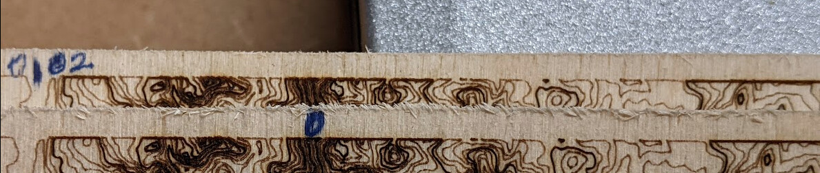
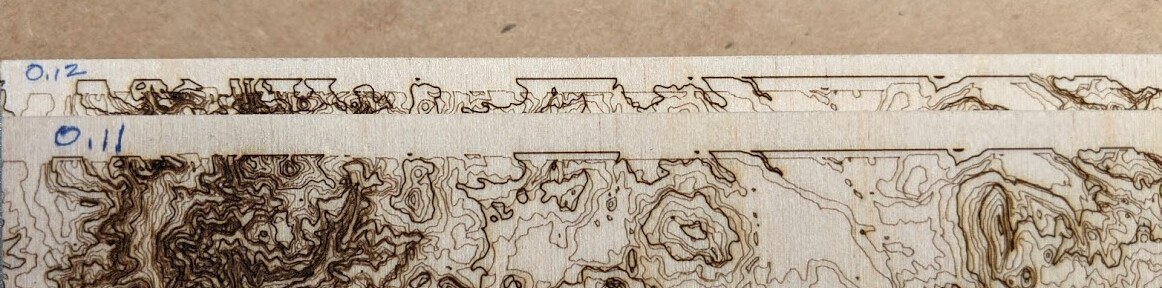
It’s worth mentioning that there is slop in the X axis of approximately 0.11mm, which is what I was attempting to correct with backlash compensation. However, without any firmware fixes it seems like better performance is had by disabling all backlash compensation.
On the 0.12mm test the minimum and maximum deviation between the overlays ranges from 0.5mm to 2.0mm. It’s interesting how fast it diverges over time.
Next steps would be disassemble the x axis and correct the slop, and disable all backlash compensation globally, as it causes unknown divergence. Until that can be corrected, I feel backlash compensation should not be recommended to be used.
The small difference from 0 to 0.02 compared to the large difference between 0.11 to 0.12 is interesting and work diagnosing.
I’ve looked at the source relating to the backlash compensation implementation and I haven’t yet identified any candidates that would explain this behavior.
@Brent113, is there a way that this could be converted into a universal test that could be run on devices around the world?
I daresay that the results are likely to be different which may help.
I’m also wondering if there’s a way to extract the current version numbers and output those from within a running G-code file.
I’ve not yet dug into the language description for G-code, so variables may not be a thing. (Extracting data remotely and generating G-code on the fly might be several levels of complexity too high.)
That does lead me to contemplate an external tool that communicates via a serial port to run a whole suite of calibration procedures.
Some time ago, I had a somewhat similar problem with y-axis drift on my Snapmaker 1. It turned out to be some slippage in the shaft coupler between the y-axis stepper motor and the y-axis threaded rod. Tightening the set screws on the coupler solved the problem.
Some of the slop may be inherent in the way the lead nut is shaped. If the pitch diameter of the lead nut is a bit larger than that of the lead screw, there’s inherent backlash. This remains true even if the pitch of both the nut and screw were perfect. This may be compensated by using a pair of lead nuts, one bearing on one thread face and the other bearing on the one opposite it, on the other side of the groove. For light duty, spring-loading is acceptable. For heavier duty, the distance between faces is adjustable.
The most common way of measuring pitch diameter is the three-wire method. It requires wires of accurately-known diameter. Gaging the pitch diameter of an internal diameter is much more complicated. Here’s an article to give an idea why. It may well not be worth trying to diagnose the existing lead nuts by measurement.
This looks like one of those cases where the easiest fix may be to replace the lead nut with a more accurate one. The pitch diameter of the lead screw can be measured accurately, and a nut machined to match. An alternative is to add a spring-loaded second nut, which would decrease the total travel. Other configurations are also possible. On the other hand, once you’re making new lead nuts, you have to wonder whether you’re still working on the right problem, or even the right machine.
There’s an absolute value function in add_backlash_correction_steps. If the total error is greater than this, there’s no problem. If it’s not, this will send the residual error negative, which is probably wrong. This could occur in the code where there are lots of direction changes with small total travel before the next direction change. All those wiggly map lines are ideally suited for this condition to arise.
Steps are always positive because stepper direction bits are stored in a different var. I think this makes sense. I’m not really seeing how error will creep in.
Since residual_error[axis] will be a constant as none of its dependents change except when a new M425 command is issued the number of steps being added to each block SHOULD be the same.
The only thing I can think is if there’s a float error when the floating point math is converted into the residual_error long where positive values are rounded one way and negative values rounded the other inducing a difference.
Another possible source of error could be related to what looks like to be an assumption in how the backlash extra steps are actually handled. One would think those extra steps would be injected at the start of the block’s motion to take up all the backlash at the start, but it appears they are evenly spread over the entire block.
This doesn’t really explain how error accumulates, but it is a good reason to only use small values for backlash compensation. 0.02mm only adds an extra 8 steps, any error would be hardly noticeable.
I think I’m going to close this chapter and move on though. I disassembled the X axis linear module and tightened an eccentric cam that had loosened, and that resolved the excessive backlash issue. After testing the backlash is back to the factory stated 0.02mm, and that seems to work fine with software compensation.
With testing there is a noticeable difference between 0, 0.02 and 0.04, and 0.02mm is the best
So that’s interesting. There’s an extra statement in the version of the code I’ve got pulled onto my machine from a few weeks ago.
    if (error_correction) {
      block->steps[axis] += ABS(error_correction);
      residual_error[axis] -= error_correction;
    }
This is the reduction of the residual error that I was referring to. I haven’t made any serious attempt to see if this code is correct in all circumstances, to be honest. I suspect it might be defective for frequent direction changes with small motions, but that’s just a hunch based on a brief read.
That last subtraction is superfluous and will get optimized out. It only applies if the variable is defined static like it is when using backlash smoothing. But in this case it’s not and since nothing uses it after that line the compiler can optimize it out