
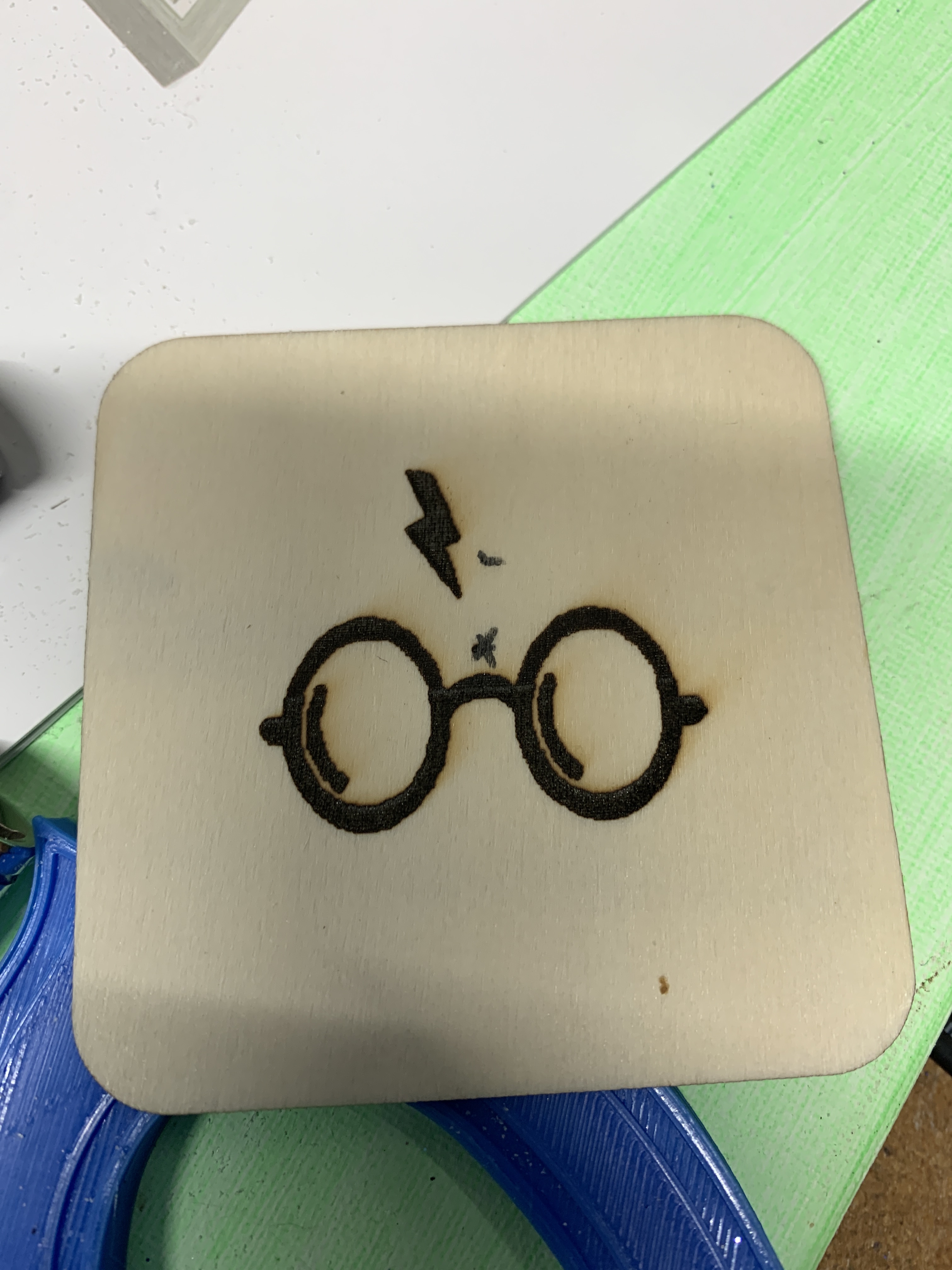
Hi Francis; I am not sure what your objectives were here but I am going to make a couple of assumptions. Everything on the plywood was supposed to be engraved (apart from a couple of biro marks indicating the centre of the plywood just above the nose bridge of the spectacles and again about 2cm above that mark next to the lightning bolt) and at 100% magnification, I can see a couple of issues. (see attached 100% magnification image)
The image looks to be burned too deeply so you should be able to reduce the power of the laser beam. Was this image created at 100% power? The brown staining of the wood has left what appears to be diagonal smoke stains moving from lower left to upper right of the spectacles. Making a lot of smoke when cutting is a problem that can usually be eliminated by careful choice of power settings and work speed. The cutting beam has to be strong enough to mark the wood and move fast enough not to scorch the workpiece, as can be seen in your image.

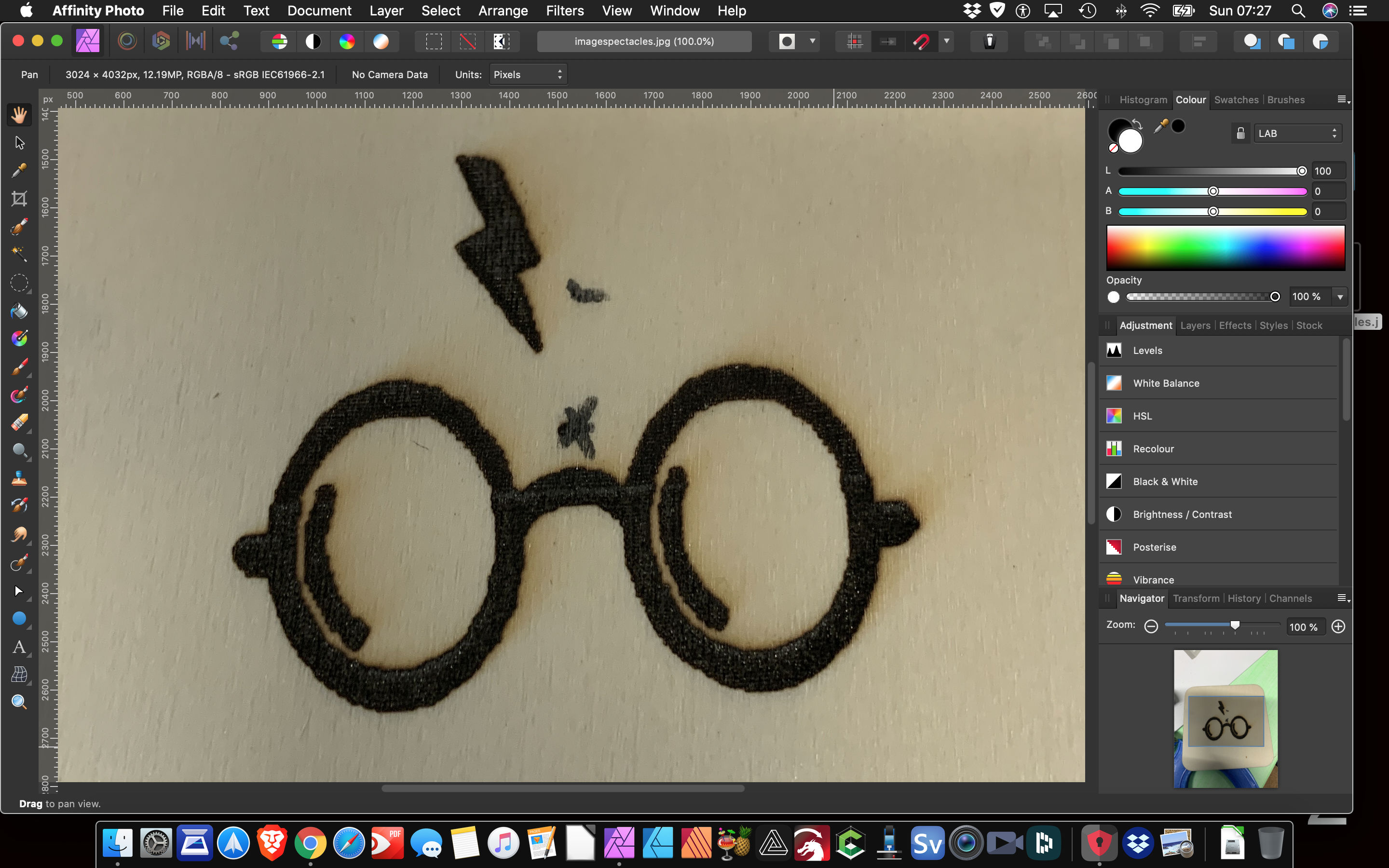
The image above at 400% magnification, lets you see what you have produced… in a manner that lets you analyse it more clearly. At the correct viewing distance you will notice very distinct horizontal lines which are very noticeable at the upper right edge of your engraved image. To achieve much flatter look to the burn, you could do with applying less power to the laser beam.
The edges of the burned image are indistinct and remind me more of a sketch rather than an image that has the clean edges of a laser cut. In general terms, the fuzzy outline of your image does not suggest it has been transferred correctly from the software to the laser beam. the next image is a letter created in software and burned into the endgrain of a wooden cube. Despite the hardened endgrain not being cut buy the laser beam, the letter looks sharply defined. There is no associated edge scorching or smoke staining.

Laser power and speed of movement of the module head are inextricably connected and each aspect of cutting/etching/engraving cannot be applied in isolation, without regarding the other parameters which you can control. The wood also plays a part in the equation and its hardness and dampness will have an effect on how the laser beam does its work.
It may be stating the obvious (for which I apologise) but the starting point for your image is to ask yourself what is the endpoint that you wish to see. Have you achieved that endpoint? If not what is wrong with the image you have burned and submitted to the forum?
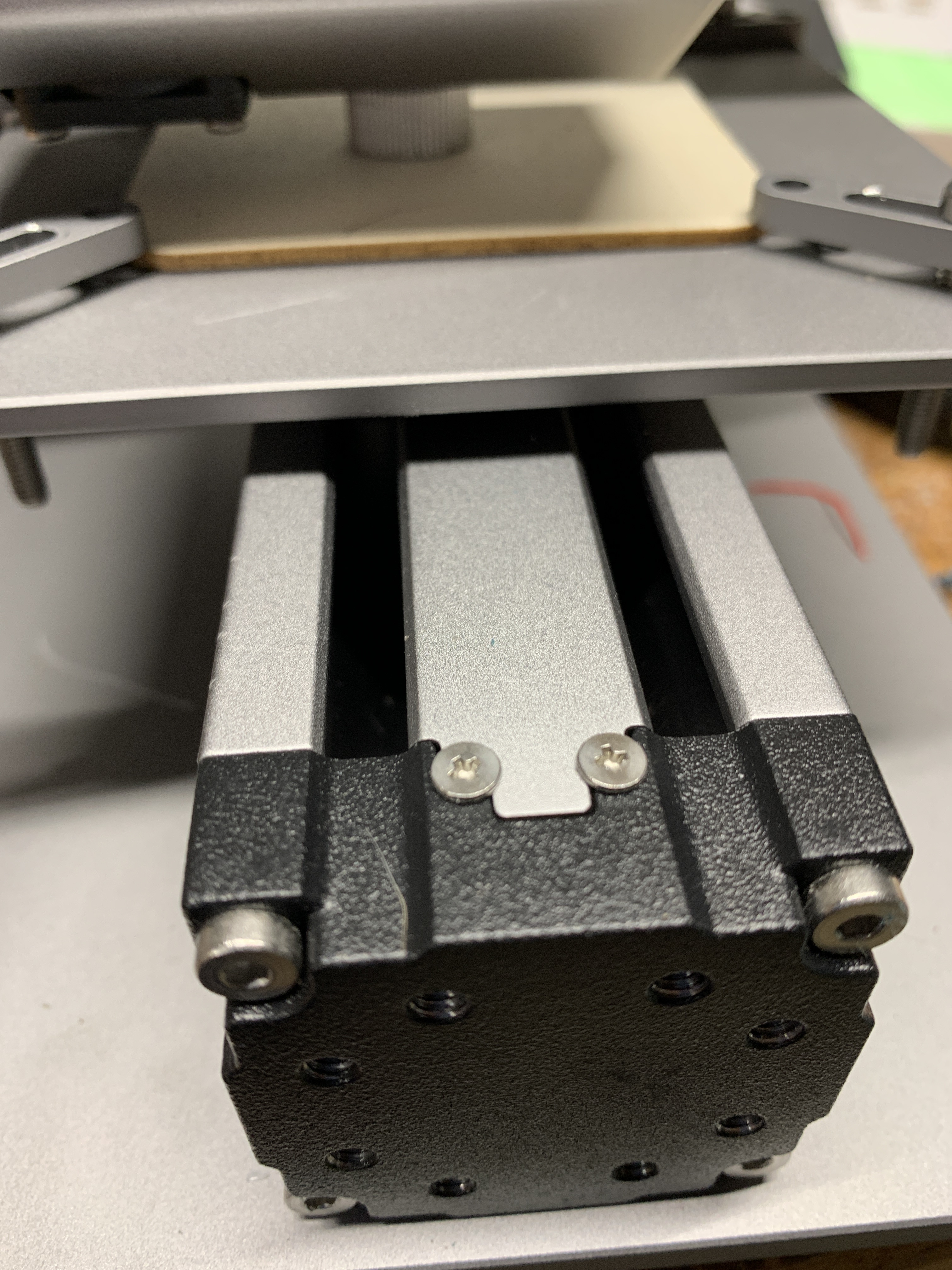
The next image is a simple star burned into 2mm thick plywood, which is very slightly damp because it was stored outside in a shed and the temperatures at night are falling to around 5 degrees centigrade.

The slight moisture in the plywood may have assisted with getting the result you see. A sharp line without scorching or smoke staining. The power was set to 40% and the work speed was set to 140mm/min. The laser was set to my calculated focus Z height of 38.4mm with the aperture of the lens screwed inwards as far as the thread will turn.
The final image shows you what the ideal laser beam will look like.

What may help to analyse your own image is if you were to post the file that you are using to burn the wood.
Thanks for all that info!!! When I set the laser for anything under 100% it produces a ghost image. If possible can I send a gcode to see if it’s just my laser or the software.
If it is software how do I fix this? I’m using Luban 3.8
You are welcome. I am not sure what the issue is. By all means send me the code. I would really like to have a copy of the file that you are using too. It may be the issue lies with that and I would like to run a few tests. What about the actual endpoint… is the image you posted anything like you had wanted it to be? What format are you using to process and save the image file?
Luban is not especially capable but it ought to do a better job than the one you have posted. Have you screwed the knurled lens ring in as tight as it will go? Then you need to adjust the z axis distance (plus or minus) to give you the narrowest beam that you can obtain on the workpiece.
Once you have found the narrowest beam, jog the z axis down in 10mm steps until it leaves a gap of less than 10mm between the lens housing face and the workpiece. Next switch to 1mm steps and jog the z axis down in 1mm steps until you are within 1mm of the workpiece. Finally, place a piece of paper between the flat face of the lens housing and the workpiece. Then jog the z axis downwards in 01.mm steps until you can just move the paper which will be trapped by the lens housing.
Note the number of 10mm steps then count the 1mm steps and finally count the 0.1mm steps. Add them together and the number you have calculated represents your point of best focus. Mine added up to 38.4mm and once you have found that number, you only have to place a piece of paper on the workpiece and trap it with the lens housing in the same manner as this test.
Then you add your calculated value to the distance of the z axis… when it is just touching the workpiece and jog the required distance of your measured value on the z axis (+ values). You will then be at the best focus point you can reach. Where you have measured the focal length value once, you know that the beam will be in focus without all of the jogging the Z axis up and down to try and find the correct focal length for the workpiece in use.
Which way should I screw the the ring? Also I don’t see the beam, only the dot on the piece of wood or paper. Is there a video to show explaining exactly what I’m supposed to do with the z axis?As soon as I’m home I’ll send the gcode. But no its not the desired effect. The glasses was to test to see if the laser would even work. I havent has any success with the picture I was trying to engrave. I process everything through luban.
The ring is that knurled silver ring holding the lens over the laser diode at the bottom of the laser module. You can just see it in my final image of the laser beam above. Turn it to the right to screw it further inwards and keep turning until it stops. That will shorten the focal length of the beam and permit you to make the tightest point of focus that the module can achieve.
In normal use, the beam will be all but invisible to your eye. It may be highlighted by smoke particles but in general, it is usually too bright to perceive the structure of the beam. You can take still pictures of the beam and that may help you to determine that it is not correctly focussed. The beam should describe an elongated and inverted isosceles triangle… as per my image.
I don’t know if there is a video showing how to focus the laser beam but if you follow my step by step guide, it will do that for you. As well as the Gcode, please send me the image file so that I can see why it is generating such a low resolution image.
I have turned the knob as far right as it can go, even with my camera, the only thing that i can see is the blue dot on the piece of wood underneath. I will add the picture and the gcode. 42126834_10155762350000205_751_00973054.nc (634.9 KB)
Ok, dealing with focus first… turning the knob as far as it will go, does not give you an immediately focussed dot. It just makes the process easier by changing the available focal length of the beam to a known dimension (the laser diode focal length + the strength of the correction lens). It is only one part of the focus process and once you have done that, there will be no need to do it again in the future.
The focus process has to be followed afterwards to get the dot as small as possible. That blue dot needs to have an effective size of the black dot next to the arrow on the calibration card. The beam will focus to somewhere near the size of a period in a piece of printed text. In any event, you will not be able to make the focussed dot any smaller than .5mm for that is the narrowest beam width of the blue laser diode in the module you have. One additional tip is that if you use the calibration card dot, once you are in focus, the laser beam becomes very much dimmer as the black calibration dot cuts some of the reflected light from the beam, so that you perceive the beam as being a bit darker at its tip.
The next step as far as you are concerned is to place the calibration card with the dot next to the arrow, on the workpiece and jog the z axis down until you make that dot the smallest it can be. As you get nearer to the point of focus and the dot becomes smaller, it can be much more difficult to judge its size.
Once the dot is as finely focussed as it can be, then you jog the z axis down until the lens face of the laser (the silver knob you turned) just touches the paper so it can be moved but not quite freely. Remember to jog the Z axis in appropriately sized steps as has been described in an earlier response to you. After you have counted the steps in millimetres, you will know how far above the workpiece the Z axis must be in order to achieve perfect laser beam focus for every job, without the need to calculate anything else. you will only just have to jog the Z axis from the workpiece to your predetermined focus distance.
@Edwin @JKC20 @Rainie @hyeii (TO THE SNAPMAKER TEAM: this is why Team Snapmaker should take note that this is an unnecessary, long and completely crazy process that is required for focussing the laser beam. The team should provide the information of absolute focal length of the diode and the required distance from the workpiece to the laser beam - accounting for the focal length of the lens - so that it can be a dimension that is added to the workpiece depth… as in my own calculated 38.4mm - in my view this is a very serious omission; which prevents people, who are new Snapmaker, from obtaining decent results)
Now onto the file I downloaded from your post.
Luban will not load the provided code and gives the error that it failed to parse the image. I cannot tell you why it wont load the GCode. I am using the same version of Luban as you do. Go figure. The screen grab of the error is next:
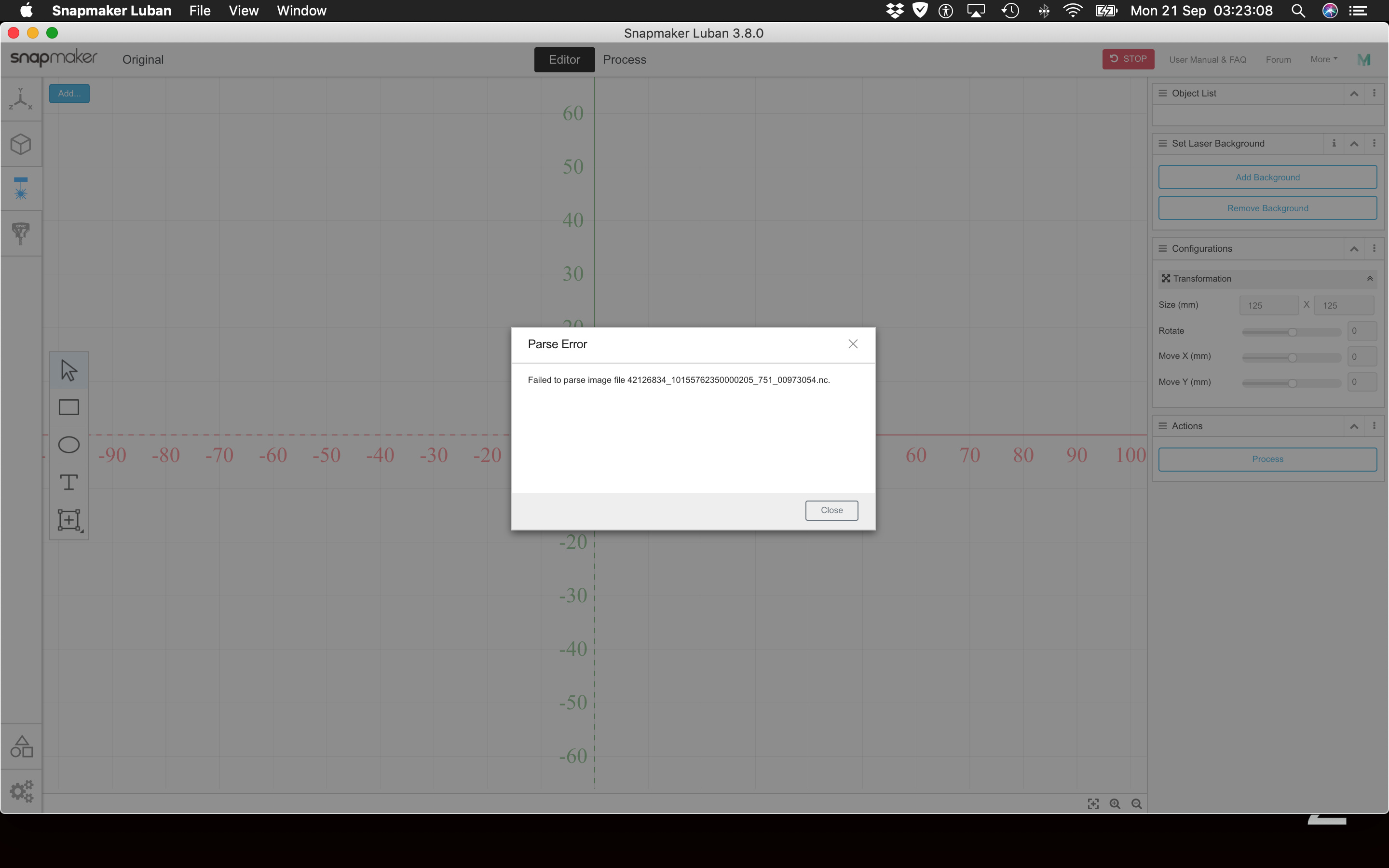
I tried several other methods of loading the code and the results were interesting. Unless I miss my guess entirely, I would say that the file is corrupt. It is certainly not indicating that it is a pair of spectacles. I use Camotics to tell me what a file can be expected to look like after it has been run. The screen grab shows an odd looking image.

There is an excellent online viewer for NC files and I uploaded your file into it. I can recommend it highly if you have a need to examine a file. it can be found here: https://ncviewer.com/
The screengrab shows the file did not upload correctly:
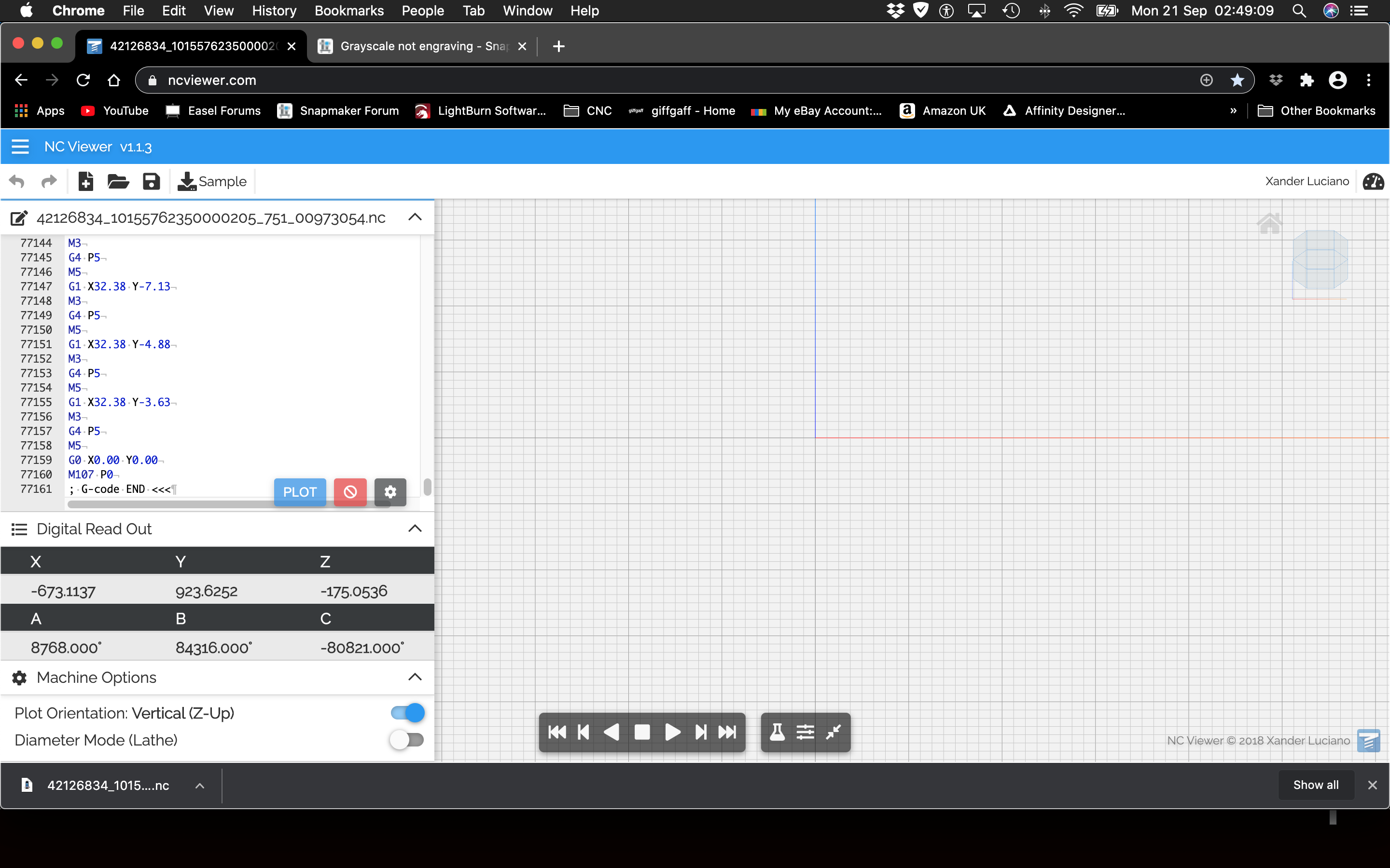
I looked at the GCode and discovered in a 158,000 word code segment that the header file was about 2,700 words in length. I stripped the header and uploaded the file to NC viewer again. This time it did load and looked identical to the Camotics generated file.

This is still not really a pair of spectacles is it? Anyway, I wait with interest for the actual image file that you sent to Luban. This will help me to analyse the reasons why you may be having this issue. As I noted before, it could be the file format of your image that is causing the issue.


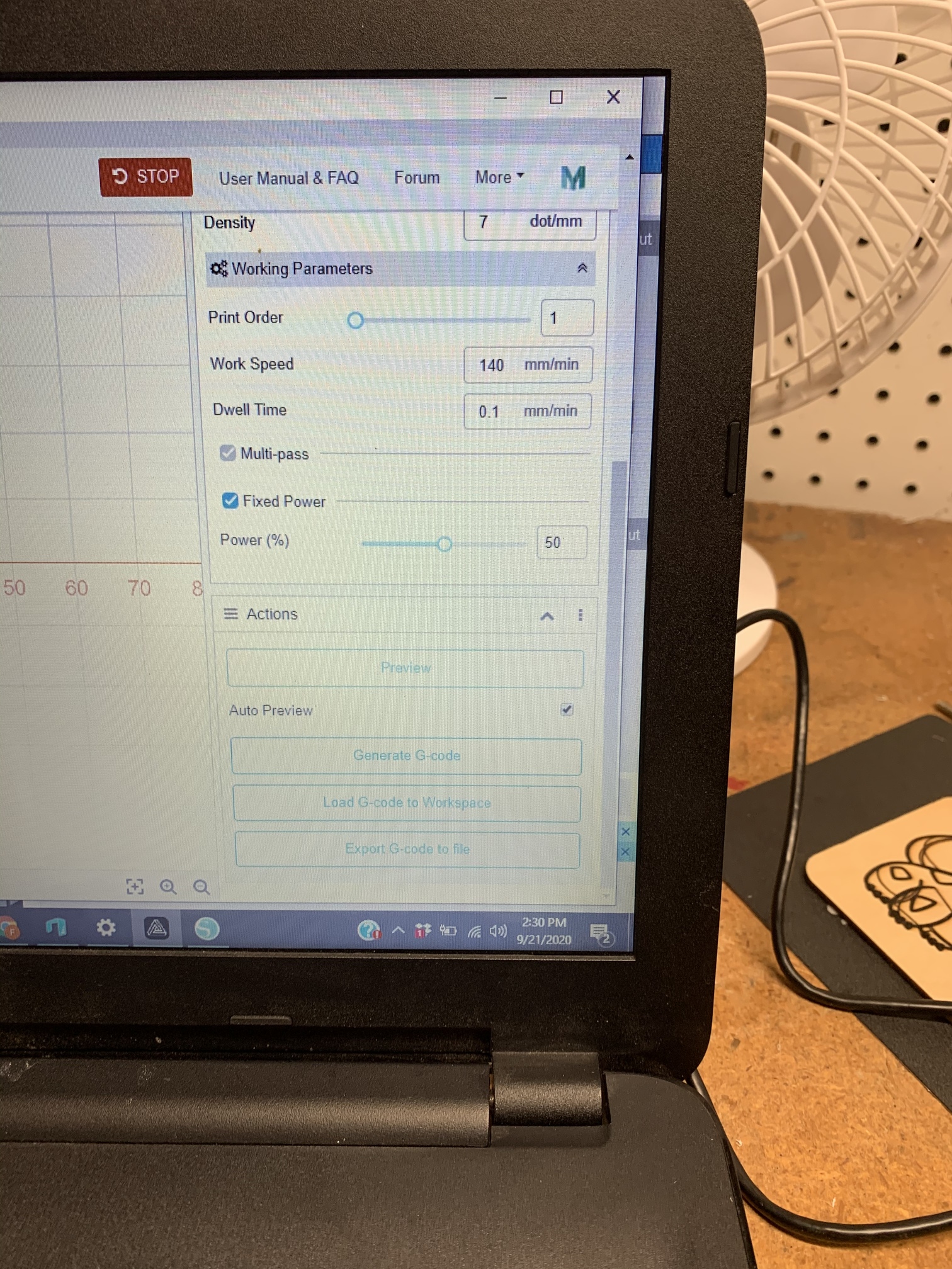
some of your text is missing because I suspect you have uploaded the images adjacent to or over it. From the settings I can read you have got the work speed set too fast for the laser power of 200mW. The jog speed is irrelevant when cutting because it is the speed that the module will move at when it is not cutting with the laser.
The workspeed is far too fast for the 50% power you have set… in fact it is too fast for the 100% power setting. Your work speed needs to be no faster than 140 mm per minute. A distance of 2500mm/min equates to the module head going from the left edge of the table to the right edge in just over 3 seconds.
Your dwell time is not compatible with that. You are asking the module to travel from one edge of the table to the other in 3 seconds but at every point of your file you want the module to stop and wait to burn the workpiece. You should probably slow the workspeed to a reasonable amount… as a general rule, if the workspeed is slow enough, you will not have to specifically ask for a particular dwell time. I tend not to set it at all.
You should place a check mark in the box marked fixed power and it will open a small dialogue where you can set the laser power. Try 100% and slow down the work speed. I would avoid the dwell time at this point. If you only change one thing at a time, you will be aware of what the change does to affect your work. Too many settings will leave you wondering how to make effective changes.
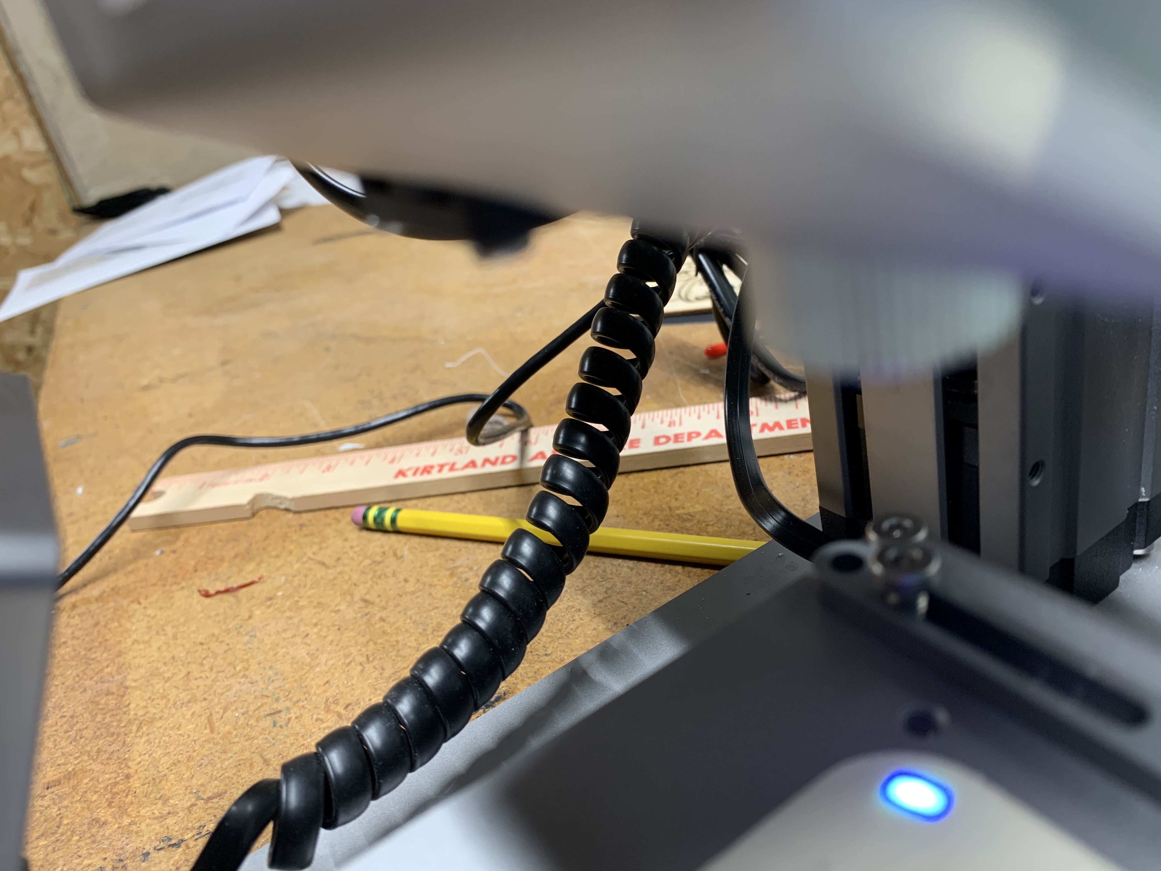
What was the calculated distance to your final point of focus. A quick check is to take a picture of the beam when it is in use. That should look like an inverted isosceles triangle. Have you got the image file for me, so that I can try and replicate your issues?
Until the laser beam is full power and running slow enough to burn the workpiece, you will not see any image.

The jog speed does not matter so you can leave that value as it is. It is the workspeed that has to change. Try 140mm/min. Dwell time can be 0 for now. Click on the fixed power checkbox and set the power to 100% that should get you some results.
What was your calculated focus point on the Z axis?
Have you got the image file you are trying to burn?

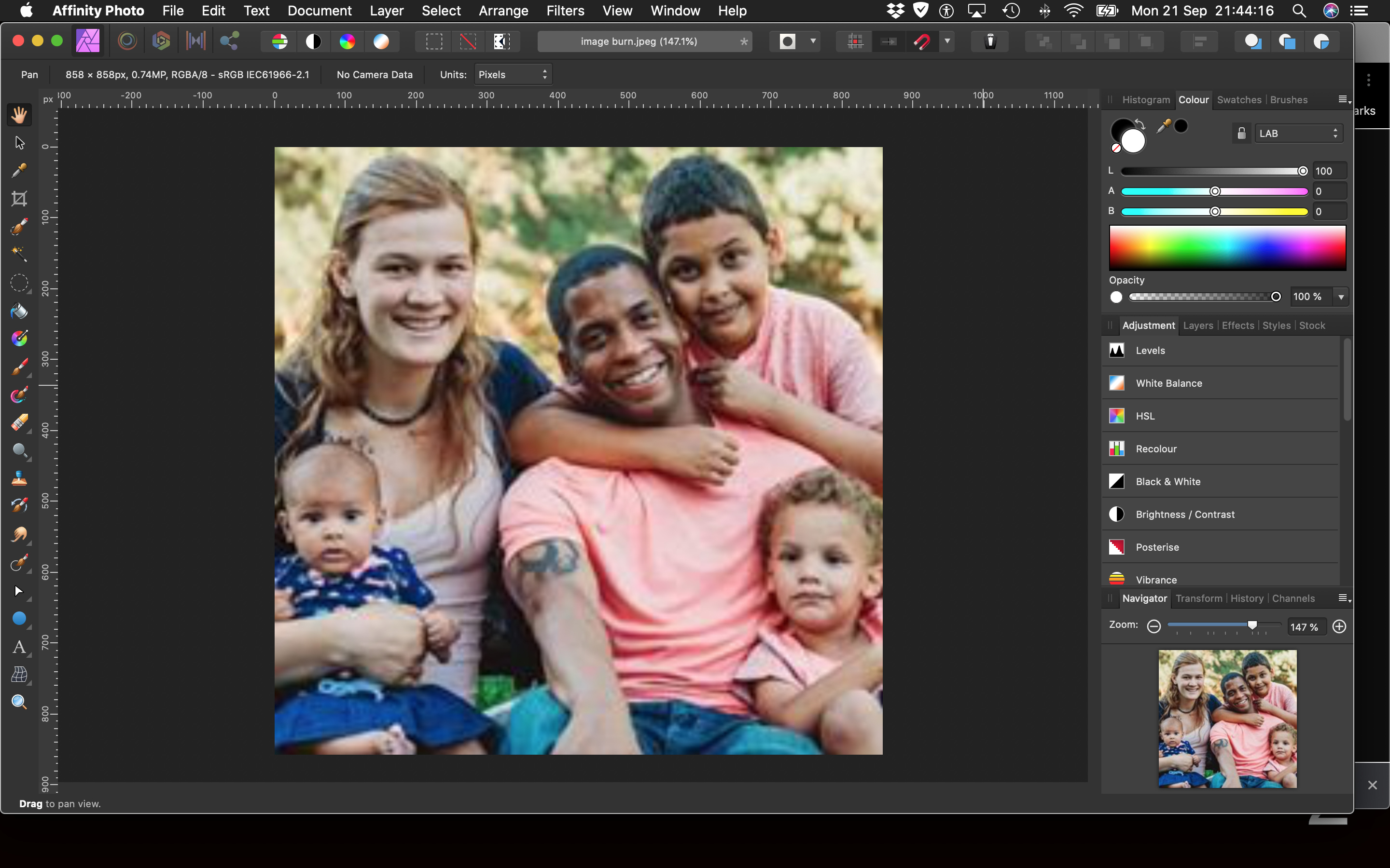
This is the photo i was trying to burn.
I did the yoda one earlier.
Also I did change to those settings and it still doesnt produce anything on the wood.
Ok, I think the use of Luban to burn this image will take a few more adjustments. What I would like to see is the image that we started with… the spectacles that Luban was chewing up the GCode for and that you could not burn without it looking quite fuzzy. I will look at this file in the mean time and see why Luban is not having it.
The one possibility which I don’t want to consider at the moment is the notion that the laser module is damaged in some way. This is why it is really important to let me see the image that you had the initial trouble with. If I can see why that image failed (I have the Luban generated code) I could get someways nearer to what is happening with your settings.
This is the image that started the trouble for me.
I did the Harry Potter glasses as a test to see if the laser was even working, and it appears that the vector image does work. I will try to do that exact picture again and show you the results
It was the vector image I was interested in because it does not have the appearance of a vector image in your picture and in the code I managed to preview in two applications. I had wanted to handle the file myself and see if I could make it do what was needed and then look at the differences in file handling between us.
Printing photographs requires a whole different level of understanding and settings adjustment.
Can I establish that you are Using Snapmaker original with Luban 3.8?
If that is the case then you only have a maximum table size of 130mm square and to hold your wood in place, you could use double sided tape. That gives you a maximum size of 130mm square. Now the Snapmaker laser module will not extend quite that far… in my recall the maximum size you can burn is 125mm square.
The image you posted is a 72dpi image (don’t worry about the terms or the numbers for the moment) It is widely accepted that for an image to print well it will need to be printed at 300 dpi resolution. This resolution will be enough so that the eye will not resolve any imperfections in the image file.
125mm is 4.92 inches in length. (at 300 dpi to 1 inch)
4.92 x 300 (dpi) = 1476 (pixels) x 1476
1476 x 1476 = 2,178,576 pixels at 300 dpi.
That calculation tells you this: You will need an image containing over 2 million pixels in the image for it to print at 4.9 inches and look good.
We now know that 300 dpi is required for every inch of image measurement. Your 72 dpi image contains 206 pixels along one edge and as it is a square image that means that it contains just 42,436 pixels (206 x 206). This is too small to print well at a size larger than 2/3rds of an inch square.
The number of pixels it needs to print at 4.92 inches square and what it has actually got are vastly different. Your image has only 1.95% of the pixels it needs to print at 300 dpi for the the full 125mm square of the SM1 table.

The image above is a screen shot of your image file at 100% size as it is now at 72.dpi. This is far too small to assist you to get a good result.
The next image is increasing the size to 300 dpi for the whole file… now the image is normal size but it has lost all of the valuable detail.
Vector files do not have this problem which is why I wanted to work with the Harry Potter Spectacles.
I will send the vector file when I return home. So the picture I sent, what do u need to do for it?
OK. Thank you for that. I await that vector file with interest. If it is not corrupt, I should be able to make a perfect copy of the image and send you the GCode that I know to be working. As well as that I can send you all of the settings you need to reproduce it. May I know what size you were producing that vector image at?
The image you have sent is far too small and too low in resolution. Please tell me what size you would like to reproduce that image at. It does not have enough pixels to be used in any standard image transfer software. Have you got any access to the original image? Whoever made the image, do they still have it on their camera? The original file can be used in its original state after a little post processing to get it enlarged to the appropriate pixel density.
Have you also got the number for me (in mm) that you calculated for the absolute zero for the focal length of your laser plus lens?

I have attached the vector image i had used. I hope that helps you out.
Also I just want the picture in a good resolution that i can engrave it in. I dont speak with the photographer anymore who took the picture. Also should i stick to trying to do just smaller engravings? any ideas of what i can do in greyscale