Just getting a rought overview on the registry code (im blind for not seeing as its quite obvioulsy named). I think ill get my Module working as a none register module first, maybe someone is interested in making it integrated.
Still working on basic functions like OLED and such. FRAM, I2C and ADC(Temps) work, just no way of displaying yet.
Contacted a local PCB manufacturer, not reply yet.
After not hearing from teh local supplier, JLC it is.
After surprising short time i got the PCBs deliverd today.
Now im just waiting on Mouser to ship my order so i can populate the whole thing. (Just orderd one set to test first then get more if there is need/interest, or if i kill parts due to mistakes. 


4 Likes
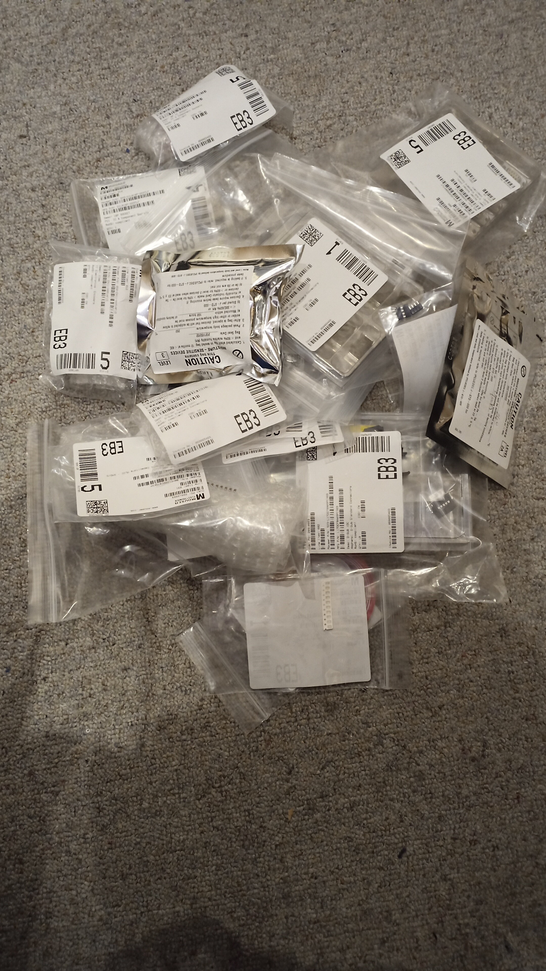
Hehe, Mouser deliverd. BUT i didnt know that PTC fuses and soem other components have to be kept at a certain moisture level to prvent problems. which will become one if i open them  What could go wrong if i let them lay around open. Its for Hobby not comertial stuff so standarts are not that big of an issue, i hope.
There are probably much more knowledgeable people on this forum than I am. How I understood it, it’s mostly to protect these parts when using reflow soldering. So they don’t break because of any steam trying to violently escape at those high temperatures of the reflow oven.
So I wouldn’t really worry about it that much for hobby purposes. Will you be reflowing or soldering? Store them with some desiccant until you will be using them.
2 Likes
Handsoldering should be a issue then as the steam can leave “without issue” as its nto suberged in a pool of solder. or ateast i hope my skills are not gogin to head in that direction
It’s probably less likely. There’s still a chance of a lot of heat building up as you’re heating the leads. But I assume you won’t be wearing clothes suitable to prevent ESD and have a floor that is created to avoid ESD etc either 
There’s always a chance it goes wrong, but for home-use purposes, I wouldn’t worry about it. (Unless you live in hot swampy region with 100% relative humidity, and even then).
I have been trying to follow this, and I don’t really understand what specifically your new module is going to be doing.
Can you enlighten me please? I am not very sharp and its really neat to see your progress.
I have a bit of the same issue Moose, im not 100% sure what i want to do with it either
But sofar it has two CAN interfaces on it to interface to the SN2 and provide a “separate” bus for extensions, currently all the messages are sent form one to the other bus. It has 8-Channel ADC for Temperature readings on the linearmodules (two are not used and spare). Th emodule has a OLED screen to show things, a buzzer to be loud, two buttons and a rotary encoder for menu movement. And a 64Kbit storage chip to save things to.
1 Like
I like the way you are doing those things ![]()
1 Like
Well, the options are there. i dotn know if someone is interested in adding their own module in the future. the Teensy code is currently barely acaptable as its mainly examplecode for the differrent parts and my trying functions out. Will push to Github at somepoint, not worth it currently.
maybe you could make one of those conveyor belts for it for infinite length or something
or come up with a module to draw with food
Im not gogin to look into Foodgrade stuff tomuch things to go wrong.
Conveyor would be possible, strap a kaptonfoil over the heated bed and move it over when print is done.
basicly this Infinite Conveyor Belt 3D Printer Mk III - YouTube
hehe i guess you could use it as an in between for a more powerful laser too, get a real strong co2 laser or something
Empty 10PM

2h later, everything fitted, Chips arent on yet, to check powerrails and such for shorts or other issus.
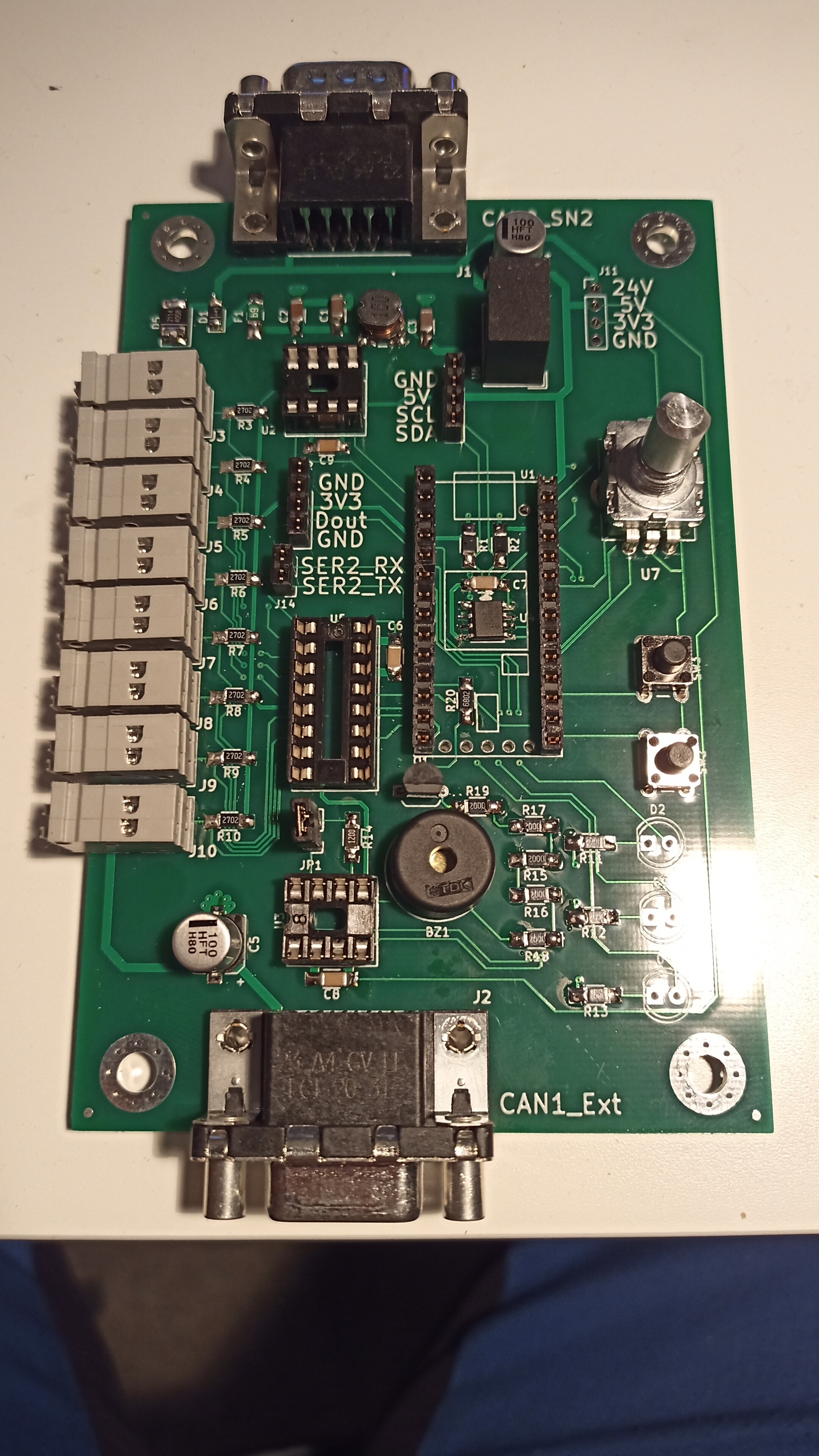
Problems found sofar:
- GND plain makes GND pads look realy bad on solderblobiness
- My Handsoldering is questionable
- the Buzzer is the wrong footprint
- the Socketstrips the teensy will be in are nto agood diea to cut, they break and now the top right pin of them is broken and looks bad.
But, sofar so good, tomorrow ahead with Powering it up first time.
With everything on wil follow then.
maybe with the first black components shortly after
3 Likes
Yeah, black is beautifull  (!!!No political statement!!!)
But to the point, nice work, I get my fingers crossed for you and hopefully it works!!!
Checked the powerrails a while ago, Teensy gets power by itself with just beeing connected to the SN2 system from the 24V to 5V regulator.
What Works:
- Buttons
- LEDs
- Buzzer
- FRAM (The selftest is good, didnt store Datayet)
- ADC (Channel 5 doesnt, investigating that currently)
What doenst work
- Rotary encoder (looses steps if rotated to fast (debouncing isnt correct yet)
- Menu for Screen (not implemented)
Things to change for Rev2:
- Discharge Resistors for Caps
- TVS diodes for CANbus
- Mountinghole positions
- DCDC-Converter and OLED header Placement
- Different Transistor for Buzzer
Anything else "obviously wrong form what you’ve seen sofar my friends?
Mountingholes may get a rework aswell to be either SN2 compatible or be a standart-ish format.
Im also open for things that should get implemented on the Module software wise. The board itself is already quite cramped.

2 Likes
Maybe you can add some PWM or 0-10V to controll a new heat bed?
i guess that you might not have the space anymore for some terminals
unless those grey things are terminals i dont know what those are actually.
I do have 2 pins left over. So possibly could add tow pwm channels. Are Optocopplers enough? So you would need still an external driver for the actual load of the heatbed.
Although having a second module doing just the PID and heating controlle would sorta make more sens. Would have its own Option for Powersupply, own CANbus stuff, more space for bigger driver mosfet and such. should be possible with a relativly “small” MCU.
Yes the gray things are terminals. The tempsensors are going to be connected there.
ADC Pins are now on a D-Sub instead of Terminal blocks. Optocouper above the new D Sub with a terminal next to it. Opto is a TLP785.
Now for Hardware changes, ill have space Problems.

3 Likes
This is some great work, One of these days when I get some time I would really like to dive into this. I’ve really been looking into the Duet3 boards for a project I’m working on now. I’m thinking at some point of trying to get their tool boards, which use CAN, to add custom devices to the SM.