For the laser, the latest Luban has DXF import function. The origin however is moved to centre the drawing. The developers are working on the ability to use the DXF origin. This will help to have a fixed workspace origin related to the DXF
Maybe a dumb question, I’m a Software vs Mechanical Engineer  . How do you validate the platform is level itself? vs the bed plate that screws on top of it?
For example if I take off the print surface e.g. magnetic bed, I can measure against the bed plate with a probe and it will reveal a large delta. How do I know if it’s the bed plate vs say the platform holding it?
Also there are a lot of people putting a lot of effort at their own expense into fixing the SM 2, I would like to see more engagement from SM team and acknowledgment of these problems, it’s way more than a few people.
1 Like
Hi @Dojima
It may help to strike up a conversation with knowledgeable Tony @Tone
Have a great day
Doug
1 Like
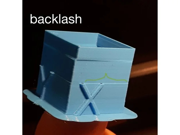
You can do that but you’re still going to have to use the leveling routines because the bed itself will have some variation. Some people have “shimmed” the bed so it’s close to level. All that still can’t compensate for play and backlash in the X,Y & Z. The best thing to do for play is tighten up the axes modules. If you tighten them up too much they will wear out faster. It’s a fairly fine art to get them just right and even then the inherit design will still have some play or flex under load. Backlash can be compensated for in the software IF SNAPMAKER WOULD JUST TURN IT ON IN THE MARLIN CODE! Hint Hint. Just let the user decide if they want it on, it can be off by default. (@whimsycwd,)
Validating that it is level is just a matter of running a dial indicator mounted on the X-axis over the surface. If you do that with the leveling turned off, you’ll see just how level it is. With leveling on, it’s just a combination of how level it really is and how well the software is leveling it. (Which can be off) I think the larger your leveling matrix is, the closer it will be able to model it but it also takes more work.
6 Likes
thank you @Tone
Doug
Hi, @Tone Please check M425.cpp,I think BACKLASH_COMPENSATION is on by default. I will ask someone to check it again. to see if we have broke it by accident, somehow.

We did do some research to understand this part code of Marlin last year. We conclude that it did have some effect. But it won’t be the most dominate factor in our trial experiment.
- Backlash compensation | Marlin Firmware
- https://github.com/MarlinFirmware/Marlin/pull/11061
- By LULZBOT
- Discussion
- [FR] Axis Backlash / Hysteresis Compensation (Code is Ready) · Issue #7579 · MarlinFirmware/Marlin · GitHub
- Yet Another Callibration Cube 20mm by rafaljot - Thingiverse
2 Likes
@whimsycwd David, yes, I discovered that by doing a compare on the source code. I don’t think it is “on” by default but it is enabled which lets us turn it on if we need to. I don’t recall seeing that mentioned in the release notes but I could have missed it. I’ll go back and read them again. It may be used in the leveling routines which could help out there. I would encourage your team to be very complete in describing what has changed in the release notes. I’m also glad to see what their future plans and priorities are, that lets us see the direction things are going and let’s us comment on them. The more communication the better. THANKS.
2 Likes
@Tone
Hi Tone, this is Scott form Snapmaker FW team. The main reason didn’t mention BACKLASH in release note, is that we think this feature is not completely enabled in our machine. As you said, users need to turn it on by themselves.
“Completely” means we need to perform enough tests to make sure it is effective and safe for most users. But recently, we focus on code refactoring, and preparing for FW open source. For now we have enabled FreeRTOS V10.3 in FW and testing its stability&reliability. We will continue to optimize the FW feature in next cycle.
Thanks
Scott
3 Likes
@scotthuang, Thanks for the reply. You really should solicit some of the more experienced users in the forum to help flesh out some of these features. Is there a “lead” engineer on the FW team? Who is it that coordinates how FW, Luban, and the Touch Screen interact?
I’m excited to see how FreeRTOS works out. Do you have a list of things to implement or change once you have it refactored?
4 Likes
Hi, I’m going for grave digging a little.
@hyeii (@staff)
I there a place where you can find all the technical drawings for the machine?
I want to add linear rails to the Y-axis platform, to support the far ends of the platform for cnc machining. The designing would be much smoother with a cad model or at least a set of drawings to remodel the relevant parts.
My problem :
On machining hard wood parts I can hear my cnc bit scrapping across the surface but not removing any material. When going deeper it still won’t go into the material but push the platform down if you have a large workpiece on the far end of the platform. At some point the bit will cut but then it will go in very deep.
By supporting the far ends of the platform on a linear bearing this problem will disappear.
I’m looking forward to your reply.
Regards
That would be nice, but I think there is no place you can get them


You can learn more about the machine via this link.
@Edwin Hi Edwin, thats nice, but I think @Melanchrom means real CAD drawings.
BTW: I am very pleased to see you so often here the last weeks!
I am sorry that we cannot offer the CAD file of the heated bed now.
Here I can share you the dimensions of the A350 print sheet.

1 Like
@Melanchrom
@hyeii is not in our company now.
Thank you for the dimensions and the information.
is there an official footprint for the A350 (and others)?
Basically, the amount of space required by the machine in operation. This would be X (unchanged), Y (with full table travel in both directions), and Z (with 1 kg spool ?). The idea is to document how much space is required by the machine when placed on a bench, building a stand, etc.
Here are the numbers I have so far :
X : 512mm (20")
Y : 753mm (29") - based on Y travel from 506mm (19.9") to 660mm (26")
Z : 680mm (26.75") - based on spool diameter 200mm
…which would make for a footprint, rounding up in imperial, of 20x29x27. I have not included the power supply as it could be mounted to the gantry, though its dimensions should probably be included.
The official enclosure is 32 x 25 x 24, though that may be swapping the X and the Y.
Is that 334 x 364 or 334 x 361 ???
Not really clear… and if I zoom in it gets distorted even more
